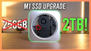
Upgrading Apple Silicon Soldered SSDs
Apr 24, 2024In this video, I'll walk you through the entire process of
upgrading
thesoldered
storage on this Apple MacBook Air M1. Now, if we go ahead and take a look at the specifications here, you can see that this seems to be a normal thing. uh M1 MacBook Air uh base model, of course, with 8 gigs of RAM, but in fact, this model is a little strange because, instead of having what I assumed was the base configuration of 256 gigs of storagesoldered
on, this machine , as you can see here it only has 128 gigs of storage installed. At first I thought this was quite strange.
I didn't even realize this machine existed but what I found out is that this configuration is what is called the educational model and I assume it was only offered to schools or something but it also has a special nand configuration of only 128 gigs of internal storage, which is basically nothing in today's computing world, but in addition to only having 128 gigs of storage, this machine also only has one nand installed on the board. where of course you have provisions for two NSs so what we're going to do in this video is upgrade the onboard storage from its original single nand configuration and install two single nand nans that look like this um.

More Interesting Facts About,
upgrading apple silicon soldered ssds...
This guide will cover all non-M1 Pro and M1 Max M1 Ultra M1 machines, but will also cover potentially any of the M2 machines and potentially the M3 machines, although some of the M2 machines and I believe all M3 machines. uh I used different nans uh than these N style BGA 110 that I have here uh, but in theory the same process should be applied, I will do it with different chips and when I say only normal M1 machines and normal M2 machines and not the M1 Max Ultra Pro um I mean because these machines only have provisions for two nans, which makes the maximum you can install two terabytes, because the largest n that they make for these are actually one terabyte each, so in this guide I will show you all. the nuances and all the processes required to upgrade one of these M1 or M2 machines that only has two nans on the board, so with that, the first thing I'm going to do is turn off this machine, open it up and I'll remove the logic board and I'll show you exactly what we are going to work with here.

In the case of this one, there is only one nand installed, so as you can see here, I have the board. out of the chassis and you can immediately see that it looks like someone has worked on this board in the past and messed up all these capacitors here, I mean they're all on the same rail so it's not really like that. It doesn't matter that they are like that, but it's still kind of funny, anyway, this board was sent to me or this machine was sent to me by someone to do this upgrade, so it's not mine, but I'll probably do it. clean them up, you know, once you're done with the update because the board still works fine as is, but immediately what you can see here is that there's a populated nand and an unpopulated nan, so of course you're going to have a single 128 GB nand on this board, uh, because of course this is a 120 8 gab configuration, um, and you might think that you could just upgrade this board by just taking a new nand and soldering it on these pads and, unfortunately, that that would be everything. that won't work for two reasons: A because the firmware for this nand tells the machine that there is only one nand so if you add a second one it won't restore um and B if we go ahead and flip the board over. here and take a look at the back, here you can see that there are a bunch of components in this area behind that second unpopulated Nan pad, a set of Nan pads there that are not populated and you can see that there are quite a few of them.

Now, if I go ahead and grab another board here, you can see that this one already has two nans installed, but if we go ahead and take a look at the back of this one, in that same place, you can see that all of those components that were. The ones that are missing on the other board are populated on this board, so of course there are a bunch of resistors and capacitors in this place, just over here one is missing I think, but there are quite a few more components in that area that need. needs to be completed for that second Nan chip to actually work, so go ahead and take a look at that again and yes, you can see how many components are not populated there and in fact, if we go ahead and take a look at the schematic, I'll show you how to identify those components and get the correct values and so on, so if you don't have a donor board like me, you can buy those components new like Mouser or something and install them on these pads. let me show you the schematic real quick and I'll show you what to look for to determine what components are needed.
So I opened the schematic on my computer, as you can see here, to determine the components you need. you need to reinstall to get this second nand function, you need to look for this string right here, at least in the case of the double nand or the two nand boards like these, it will be called ssd2 L and I think what that means. are they ssd2 landing pads or maybe two layers, uh, I don't know exactly, but I'm pretty sure they're two landing pads, that's what that means, so as you can see, any component that has that label ssd2 L is a component that is not going to be present on the board is if this nand is not present on the board, uh, so you can see some of the most important components here are these four AC coupling capacitors here these AC coupling capacitors .22 microfarads um and most of these components should be shown um the footprint that these are for some reason no uh but this resistor yeah you can see o201 uh this capacitor here o201 um and then of course we have a bunch of other components like these two pull down resistors here also O2 21s uh, we have an inductor here, uh, we have more capacitors here.
A bunch more o201 10402, you can see there, um, and then a power capacitor here and a few more capacitors on that power rail and more here and like you. I can see that there are quite a few components, including these here, these pull-down resistors or a pullup resistor, a pull-down resistor, that need to be present, so it's not an insignificant amount of work to reinstall all of these components, but of course, I need to do it. to allow that second Nan to work once we install it, so the first thing I'm going to do here before installing all of these components is to remove the original nand from the board and the reason.
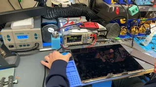
I'm going to do that because removing that nand a requires not using the preheater due to the amount of pressure we have to remove to remove it due to insufficient filler used to secure it to the board and B I also have to heat the board to fairly high temperatures, around 380 to 400°C, and that could cause the components that we install using leaded solder to melt and come off the board as we work, so the first thing we do is remove the original nand and then from there we can start the process of installing these missing components as well as the two new NSs that need to be installed, so with that we'll go ahead and start that process okay, as well as You can see here.
I have the board in my workspace here and to do this removal you will need something like this and this is an underfill removal tool so we are on it right now. It's basically a small double-ended one. The exact handle of the knife is what it most closely resembles, I would say, um, but I have two attachments here right now, um, on this end, I have a little hook attachment, as you can see, and what I'm going to use this for is. I'm going to use it to scrape off the bottom filler around the perimeter of the chip.
And of course, we can't do that yet until the board is, or this chip and the board around it are quite hot, which of course will get hot. with the hot air, um, but on this end I have kind of a small pointed tool, but not sharp on the end, just kind of a round tip, as you can see there, and what I'm going to use this one for is one time. . the chip is at the melting temperature of the solder. I'm going to glue this under the chip to separate the bottom filler that holds this chip to the board, it's basically going to be glued to the board so it's not as simple as just heating it up and waiting. until the solder melts and then just lifting it up with a pair of tweezers like I have done many times in the past, because it doesn't have enough filler it takes a little bit of force to remove it so the first thing we need to do is get some weight on the board, so I have this weight here.
You can see it's a hacko thing, but of course it's designed to hold a board, but I'm just going to use it to press the board against my workspace here so that it doesn't move on me because it requires a little bit of force to use this. tool, so the next thing we need to do is just start heating up and get ready to remove the underfill around the perimeter of this chip, so I'm going to turn my hot air on to about 300 to 350°C for now, which won't be enough to melt the solder, with the board not on a preheater like this, so I'll go ahead and turn that on. turn the air pressure up a bit to around 60% and then set the hot air to about 350° and with the hot air set to around 350 uh you just want to use it to preheat the board in this area and mainly of course.
Focus the heat on the chip that you're trying to remove, so we're going to let it heat up a little bit and also on this particular board you want to remove this little piece here, otherwise it's going to melt. So we're going to remove it and of course we'll put it back in once we're done. I'm not sure it's really necessary, but I'm going to put it back in, so we'll wait until we get a good amount of heat on this chip. and then once you think it's nice and hot you can start taking your little hook tool like this one and just start scraping the bottom filling around the edge of the chip and if you do it correctly you should see it start to come off .
Now don't press too hard. with this tool you will damage the chip or remove the solder mask from the board, which you don't want to do, so we'll just take that and separate the bottom filler, so it takes a little bit of force, but don't do it. I don't use too much like I said so now once the underfill is removed I will increase the hot air temperature to about 380°C and yes I realize it is quite hot but the reason I am using that temperature is because We're not using a preheater and I should also note that we're not using flux in this and I'll explain why in a minute or I guess you'll see why in a minute but basically when you eliminate underfill like this , it basically becomes.
This little guy basically flakes off, you can see a lot of flakes already when removing them around the perimeter of the chip. And if you have flux in there, that really causes the underfill to build up and just make a big mess. the board, which of course you don't want, so we're going to let this chip heat up here for a moment and then once we think it's hot enough, we're going to start pushing this tool under the chip. And you want to have some kind of opening for it, so I have an opening for it now that the chip is not completely at melting temperature yet and you have to be very careful when you push this down because if you push down if you put it underneath and the solder it's not coming off, you're going to break the pads and of course you're not going to be able to recover from that easily so we're just going to make sure it's nice and warm and this takes a little bit of time so just take it. your time with it you can check periodically and if it feels hard to push your tool in there like it's too hard, definitely don't force it in there, but when the chip is ready to come off, when you push this down, I guess that's for the best.
The way to describe it would be like a knife through butter, not a hot knife but a cold knife through butter. I guess that's the best way to describe it, but you don't want to put too much force into it, but it shouldn't require it. it takes a little bit of force but not a lot so we just keep waiting here and start trying to push it up and sometimes when you do this you'll start to see a little bit of solder coming out of the sides of the chip. And if that happens, it's a sure indication that the solder is starting to melt under there, um, but that doesn't happen all the time and if you're having a little problem like I'm having now, just increase the temperature of the solder a little bit. air. a little bit, so I'm going to go up to about 390°, now just 10° more and you don't want to go too crazy with the heat, but you also don't want to not heat it up enough and that was enough for you to See my tools come in, it feels like butter, so make sure that while you have the tools underneath you completely heat up the entire chip and then while you're doing that you can start to slowly and carefully lift it up with your tool, now don't force it. just do this, eventually you will see the chip start to move andso the chip is now removed so go ahead and pick up the chip and place it somewhere away from the board and now I'm going to change my tool.
Here to the flat tool and I'm going to use it to clean the residual solder and residual filler mainly from the pads of the board. As you can see, I have it here now and we're just going to Use this to scrape like this, don't angle it too much, but keep it at a slight angle, a little less than 45 degrees, and that way you won't damage the board, so I still have my air at 380 I turned it back down to 380, so we're going to heat the board again to two solder fusion temperatures, of course, and you'll immediately know when the solder fusion temperatures are because the tool will otherwise get caught in the solder balls, so you can see now that this is not the case.
Now you'll just take this tool, press lightly against the board and you'll just scrape off the bottom filler. If we had flux here at this stage, this would work. They will all become one big nasty clump combined with the sticky flux, so not having flux on the board at this stage really helps a lot, you just have to be careful, don't tear the board because you will damage the pads or damage the solder mask. , okay, and this is what it looks like, you can see the underfill has been completely removed now, before I stop heating, I'm going to first remove the underfill from these capacitors right here, just in case this little mass gets in the way in the path. this and so I'm going to lower my temperature so I don't melt the solder and so I don't mess up these capacitors here and I'm just going to use my tool to remove this solder or this underfill next to these capacitors, why? they put underfill only in some capacitors.
I have no idea, and that's okay, so the next thing we need to do is use the soldering iron to remove all this residual solder and tin the pads with some new leaded solder, so I'm going to turn off the hot air. You don't want to let the board get too cold. But I'm going to turn off the hot air, let it cool, and then we'll start preparing these pads for new ones. it's going to set up nicely so the hot air cools down now, so the first thing we need to do is just apply a little bit of flux to these pads like this and I'm also going to apply a little bit here because we need to remove all of this solder.
So with the flux applied, we're just going to take some new solder and apply it to the pads, and now with our pads seasoned with some new leaded solder, we want to take our solder wick and just remove all of that solder and The reason we are doing this is so that the pads are well tinned with lead solder, which will make installation a little easier, and now that that is done, the next thing we need to do is simply clean the pads rubbing a little. alcohol and a paper towel of course, that's just to remove all the old flux, and that looks good, the pads are nice and clean, so now the next thing we need to do is prepare to install the missing components on the bottom of this nand. um and of course that will allow that second Nan to work when we install it so with that the first thing I'm going to do is bring my donor board here to remove the components um now you don't need your own board for this um the parts that I showed are all available or all listed with their values and footprints on the schematic, so you can just use that to buy those parts from any electronics distributor like Mouser or whatever, so I'm going to use a donor board because I have one right here, um, that I'm not going to use for anything else, you can see, I've already taken some parts off, like that pmic, so we're going to use it. from there, um, so I'm going to put everything together, we're going to start by removing the components from this board and then installing them on this board, so as you can see here, I have the donor board on my preheater here and I have the other board here next to it for to be able to look at it and compare it while I unsolder these components.
Now I think the easiest way to do it is to remove them all at once. although I know it seems a little strange because then I have to keep track of all of them, but I think I can place them here on my table and then I can keep them in the correct position and orientation even though they are very small. The components are mostly O20 and then I'll take them and solder them onto the other board. When I'm done, I'm going to go ahead and heat everything up here and start removing the components. There's definitely no way I can keep track of all of these components at once, so I'm going to stop here, switch to the other board, start installing on the other board, and then keep switching back and forth until I'm done. that way.
I'll do it in chunks of about 10 or 11 components each, there's about 40 components that need to be transferred and that should be just take me four four rotations here and I should be done so let's put the other board on. I'll show you how to tin all the pads and then we'll start reinstalling more components, so I'll heat up the board here with the preheater and then we'll just tin all these pads with my solder. iron to apply some lead solder to them, that will make it much easier to solder the components and then we can start soldering the components as we go, so with the flux applied, we'll just take the tip of my iron, apply some solder to it and then just go over all these pads so that's all the solder applied so now we're just going to grab the components and start installing okay.
I think the installation will be a little bit easier to remove the preheater from the board, so that's what I'm going to do because the preheater makes my hands too hot, and that's all those components, so it's 10 Of them, I actually think of 12 components in total. Now I just need to do that four more times with 10 more components each time and I'll have it completely ready, so I'll do it off camera, install all the components and we'll go from there, just like you. I can see that I have reinstalled all the components. You can see this is where the components are supposed to be and as you can see everything is now installed or you probably can't tell but I've been through this.
It's pretty hard to show it here, but I've gone through all of this and I've checked everything and everything looks good and yeah, we should be ready to install some nans on this board and in theory we should be ready so let's go. I mount the camera back on the tripod and we're going to start the process of reballing the n and getting ready to install them on this board, so as you can see, I have my chips here ready to start reballing, but before we do that, I just wanted to give you some information on these specific chips I have here now.
You may be able to read the part number right there and these chips are kicm 223 part number chips so these are kioxia uh one. tbte chips and when you buy these chips you will want to make sure if possible that they are brand new, unprogrammed blank chips which will be your biggest indicator on the path to success basically so if you get these blank chips don't programmed, new, it will be. You can probably install them on the board and not have any problems restoring them; however, these chips were blank and new, but I actually did some kind of experiment which I'll probably talk about in a future video, uh, but for now, I've done an experiment with these where the original firmware was overwritten. or new firmware was programmed into them, so they are no longer blank chips.
This is why I am using non-blank chips in this case. it's because I want to show you what happens when you try to do that and how to rectify that, which is actually a pretty recent development here, so if you remember in a previous video I made, I installed some non-blank chips in luk mean. Mac Mini when we did that upgrade and they didn't work now to solve that I replaced those nans with some new nans that I bought that were blank and actually one of them ended up dead which is another thing I'll get. but I've done this update many times since then, I've never had another dead Nan, so I think the likelihood of that happening again is insurmountable, uh, so anyway, with that I'm going to start reballing these chips and uh. then we will install them on the board.
I hope it doesn't work, but I'll show you how to rectify it if it doesn't, using a special programmer, so with that I'm going to start reballing to do the reball here uh, I'm just going to use a little bit of solder paste with this stencil here uh, so the first thing we're going to do is just take one of these nans and notice that it already has some solder on it, uh, I actually put This is here when I initially did the EXP experiment that I mentioned before, but the balls are still a little bit small for use with basically endless pads, so we're going to apply some additional solder to this chip via some solder. stick with this stencil uh just so the solder balls are the right size to accurately and properly solder to the board so the first thing we need to do is just stick the chip to the back of the stencil with the correct alignment, so let me do that. real quick here and to do that I'm just going to use some capton tape so I've got the nand on a capton tape here and we're just going to take it and line it up with the holes on the template and tape it down so that from here we're just going to take a little bit of solder paste and apply a little bit of it to the footprint here on the stencil, so that's probably enough there and then we're going to take this tool that I actually put on the end of my underfill tool as you can see here and simply use it to push the solder paste equally into all the holes.
Now, as I mentioned, this already has a lot of solder in it, so there won't be much solder paste on these. holes uh but there should be a little bit and uh that's all we really need in this case so once the solder paste is in all the holes we just need to turn on the hot air to about 300 C and then with We'll take a pair of curved tweezers like this one and press the template firmly against the chip. If you don't do that, there's a chance that the solder paste will run under the stencil and make some of the solder balls larger than others.
Of course, you don't want that, so once you've done that, just take the hot air here and just heat the stencil until all the solder paste melts into the holes, so as you can see there, all the solder paste. welding is completely. they melted onto their pads there, so now we'll just remove the chip from the bottom of the stencil like this and then once the chip is off the stencil, we'll apply a little more flux to it like this. and then we're just going to heat it up one more time with the hot air from the stencil and that's going to make sure that all of these solder balls are melted as expected, nice and everything looks good.
You can see that the solder balls look very nice. there, uh, they're nice and even, and there are no balls that are taller than others or bigger than others, so one thing you have to check when you do this, you have to be very careful, be very careful with this is Sometimes, when you reroll with solder paste, there are little bits of solder, um, that turn into little balls of solder that just spread everywhere, um, if you see those, and I see some, you want to clean them completely with uh. Rubbing alcohol and a paper towel, it's going to get all the flux out of there and that's also going to get rid of all those little bits of solder, so I'm going to do that real quick and then the nans are ready to install on the board.
Alright, as you can see, I've removed all the chip flow here and everything looks good, so now I'm going to do the same process with the second nand and then we'll be ready to install both. on the board, so as you can see here, I have the board on the preheater now, you can see, we have the Nan pads here, so all we have to do now is just apply some flux to these. pads, place and align the chips and then just solder them, so we'll go ahead and start doing that now, because there's no flux on the chips, we want a good amount of flux on the pads and once you have the flux on the pads there, We can just take our chips and solder them onto the board or at least align them with the board and then solder them, so we'll take one here and fix one on the MacBook Air. here of course you want to check that based on how the originals came out or of course using the board schematic so you want to try to line them up as close as possible, of course they don't have to be perfect. but you want them quite a bit and of course you can always compare them to another board if you're not sure you have one, but everything looks good so I'm going to turn the hot air on to about 300. to 330°C this time, because we have hepreheater and we have lead solder in there so I have the hot air heating up now and once that's heated we'll just start heating the chips until they're soldered onto the board so you can see one of them is already completely soldered and I'm sure you can see that one also moves into position and just like that, both chips are fully installed and now we're ready to partially.
Reassemble the system and try to restore it in dfu mode, so I'm going to connect everything and prepare it for the dfu restore and then we'll test it and see what happens, so you can see here. my restore setup goes here basically, this is just an iMac G4 that I modified and connected a Mac Mini M1 to it, as you can see I have it there, but it's not complete of course, you just know I'm the best. machine that I have for this right now, so that's what I'm going to use and here I have the MacBook Air itself, folded and with the motherboard facing out, towards us here and the reason why I did it. that's because getting this machine into dfu mode with key commands, uh, when it's in this state with a new NS this way is extremely difficult, so I'm going to show you a much easier way to get it into dfu mode , uh um, which doesn't involve using keyboard commands and works much better most of the time, so let me set it up here and I'll show you exactly. how we are going to put this machine into dfu mode so before we start here I want to show you exactly what will happen when you try to power this machine with new nans installed so I'm just going to plug it in.
USBC power here and as you can see it just loop boots over and over again, you can see the amp meter turns on and off like this, that means the device is loop booting and that's why it's very hard to get. in dfu mode with key commands, now I'm going to show you how to enter dfu mode in a different way and that is by using these jumpers here, so if you take note here, you can look at these jumpers and see if I can show them. a little bit right in the middle of the screen, you can see some jumpers, and those are actually where the buttons would normally go, they're located here, as you can see, and specifically this is the dfu button over there, however, there is a resistor in line with that button, at least one of the pads on that button, you might be able to make out those pads right here, so basically what you have to do at least on this M1 MacBook Air is before you turn it on.
I cut the top pad of this resistor or I guess the bottom, looking at it this way, to the pad of this button over there and I'm going to use a pair of pliers to do that here and you basically hold the pliers on the socket. power on and then hold until you see dfu mode appear on the host Mac so that's exactly what I'm going to do right now, okay and it was successful the machine is now in dfu mode so I'm going to go back to dfu mode. uh, iMac here or Mac Mini, whatever you want to call it, and we'll start the process of trying to restore Mac OS on the device, so you can see there that the uh MacBook is connected in dfu mode here, uh, so we're just going to try to restore it and see what happens, so I'm going to restore it to the latest version of MACC OS Sonoma that exists at the time of making this video and we'll keep an eye on both machines here, okay?
I can see the screen is on on the MacBook Air, that's a good sign now, like I said I don't expect this to work but we'll see. I just want to show you what you can do if it doesn't work right, so while you don't see that the restore has actually failed, but in fact it looks like the restore has failed. If you can make out that ammeter there, it's in that boot loop state once again, which means it's trying to start, but it can. It's not because the nans don't have the software that is expected, that means we need to reprogram the nans accordingly now, as I mentioned these were blank nans that I experimented with or have experimented with in the past. um, that's why they don't work anymore because they've been programmed with something else and there we go.
I just got an error on the screen. There you can see we got an error 9 which means it disconnected in restore mode when I didn't expect it to disconnect and the restore cannot be completed so I'm going to take the airboard out of the MacBook again, let's desolder the nans a one more time and then I'll show you exactly what's needed You need to finish off those nans to get them working once again so as you can see here I've unsoldered the nans from the device once again um and uh to move on to the next ones steps you will need. a special tool and that tool is here um this is called JC p13 programmer um actually there is a new version of this now called JCP 15 which supports BGA 110 and BGA 315 nans uh used in some M2 and M3 models uh but this is just a BGA 110 model as you can see right there, so it will work with the nans that we are using in this case, but it will not work with the nans of some of the later systems, so let me get this straight. connected to the computer and I'll show you exactly what to do before you do that.
You want to bring your grandmothers here and you want to tag them and the reason for this is because we are scheduling them. It will need to be installed in specific places on the board now, at this point it doesn't matter which nans are which CU, they are not programmed, but you want to take a marker or something and just label one of them as zero like that and the other like this that we have zero and one there, um, of course, like I said, this is only for machines that have two nans, not ones that have eight like the M1 Pro Max Ultra and M2 Pro Max and Ultra and all. that's just for the M1 standard, the M2 standard and maybe the M3 standard.
I don't remember exactly how it's set up, uh, but basically any of them with just two nans, this applies and this also only applies to kicm 223 n because the files that I have on hand, uh, the only files that I have on hand to programming are only for kicm 223 nans, so with that out of the way, I'm going to switch to the computer and show you the process of programming these nans to It can be used on MacBook Air or any other system. As you can see here, I have the JC programming software open, so the first thing you want to do is take your programmer like this and just plug it into the computer and as you can see now a little OLED panel on the side of the computer lights up.
You need to go here to Pork and make sure p133 is selected. It will show any other serial ports your system may have and once selected, select Connect, you will hear. sounds and now the programmer is ready to accept a nand, so the first thing we're going to do is put the number zero of the nand that we just labeled, so yeah, first we're going to take the alignment of the number zero of the Nan. fix one in this bottom corner where you see the little dot on the socket here and just put it in the programmer you can see it detects the kic m223 nand installed right there and just loaded it into the software so in the software here the first .
What you're going to want to do is Select Mac and you can select any model. Really do not care. I'm just going to select MacBook Pro um and now we need to write a dump to this nand now before we select. this dump I want to say a big thank you to the person who provided me with these Nan dumps and that's Giles uh from Polysoft services in France and in fact if you live in France and you want this update done on your system he does it . perform these Services and if you are in the US, I will also perform these Services, so if you want these updates performed on your machine, you can let me know if you are in the US or you can contact Guiles at Polysoft services. in France, if you live in France or even anywhere else in Europe, leaving that aside, let's write the gu dump into this nand, so since we put nand zero in the first thing we need to do is come up here and locate the gu dump.
Nan so you can see, I have these two right here, um, so a 000000 is Nan and a10 is nand one and if you're confused about which is which, you can see that they are labeled as such in the schematic. You can see this one, the one that is vertical here is a0, the one that is horizontal is a 100 and a good rule of thumb if you don't have schematics, it actually seems to be an exception in this case, but usually Nan zero is the closest. al S so um and Nan one has the furthest one, but as you can see this is an exception, so it helps to have schematics, but of course you can guess and just reschedule again, no big deal, so back to the software we use.
We're going to select a and the software will simply write that file to the nand and you can see there that it reports that the repair is complete, so now we'll just take the nand out of the programmer and take nand number one. we labeled the number one and put it in the programmer wait for it to load it here and then just select the right data again go back to the same path here and this time we will select nand one the dump for nand one for the kicm 223 and as you can see there, the nand repair is completed.
I mentioned that I have a bad nand and I guess you might want to see what it does when we try to program it to have the correct nand. here I've labeled it with a little x, so I know it's bad, so I'm going to go ahead and put it in the programmer. At this point, everything seems fine, so we'll try to write one of the downloads and as you can see there, it reports that Nan Repair failed. I have tried updating many things on this nand and nothing works and this nand has never worked since I bought it when it was sold to me as a program. configured for the Mac Mini M1 that I initially tested it with, so n is dead and that's why it didn't work initially when I tested it in that first video, so now that we've programmed both NSs, we simply need to solder them together. on the board now in the correct positions again Nan zero goes here Nan one goes here and then we will be ready to try restoring the device one more time so as you can see there I have the Nan soldered back onto the board uh I already have the machine booted in dfu mode, so let's try to restore it and see what happens.
Okay, so we have video on the MacBook Air once again and look at it, as you can see, we have a progress bar. and the progress bar is actually moving, so at this point you can be pretty sure that the nans are now fine and the machine is happy with them. The OS is now being restored on the nans. That indicates that all my welding with everyone. Those little components were good and B, the nand programming was successful as expected, so we'll sit here, wait for this to finish, and check the final results. Well, the restoration was completed successfully.
The machine is rebooting now, so let's see. what happens and look it's starting up and that's it's done so now I'm going to turn this thing off because it doesn't have a heatsink yet so it's going to run a little bit. Heat up um and then clean everything, turn on the heatsink and then set it up and see how everything looks, okay, as you can see here, I have an almost reassembled device, uh, you can see, I have all the flow. I cleaned everywhere. I reinstalled the heat sink. I haven't installed any of the connector covers yet, but I will do so in a moment.
So let's go ahead, turn it on and take a look at all the system specifications. Okay, you can see we're on the login screen here, let's go ahead and log in and there's the system, so let's move on to this Mac. You can see it has the same specs, the same 8 gigs of RAM, base model, of course. uh let's go ahead and open up disk utility and there's two terabytes of internal storage there so that's been the successful upgrade of this MacBook Air M1 from single nand with only 128 gigs of storage to dual n with two terabytes of storage now one.
What I want to point out before I end this video is that according to Giles, the guy who sent me that firmware or those dumps that I programmed into the nans of this machine, says that it is possible that the read speed or the correct speed the speed is a little bit slower than you'd expect ECT uh when you do that uh I'm not really sure why I've never tried it myself uh but what he says uh rectifies that is just adding a bunch of zeros to the whole disk so all two terabytes of zeros, which seems a little strange to me.
I could try. I won't try it in this video. But I just wanted to give you that little information in case you experiment. Some weird oddities with drive speeds I've done this once before with these firmware dumps and have never experienced any notable issues so it may or may not happen. I'm not exactly sure, but anyway with All that was done was the successful upgrade of this Apple MacBook Air M1 to 2 internal storage tablets and the demonstration of the process throughout the process, so I hope you enjoyed this video.
If you have any copyright issue, please Contact