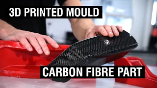
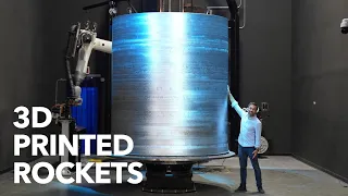
Turbo Manifold 3D Printed from Inconel Powder
Jun 02, 2021Hello, I'm Stephan Papadakis from Papadakis Racing. We're here at our race shop in Carson, California where we just finished our 3D
printed
Inkanel header for our GR super engine. This isn't actually the first 3Dprinted
metal piece we've had. We also made an aluminum intakemanifold
for the gr supra and i will link that video in the description below and this project wouldn't be possible without solidworks. They have a new connected product, solidworks, which is what we use for design. not only the 3D printed part but also the manufactured part, let's get started. I'll show you the whole process, so it was a fun project.
We used a lot of technology to make this 3D printed header the first special tool that was used was something called a pharaoh's arm and our friend Tyler came along. He's the one who ran the arm, which is a 3D scanning tool, so once he had everything set up, he started scanning the engine, the engine bay, and the way the tool works. it sends a laser and this laser through the software creates what is called a point cloud and this point cloud is essentially a bunch of small points in space that eventually become so dense that they create this virtual component that you are scanning.

More Interesting Facts About,
turbo manifold 3d printed from inconel powder...
For us, it was the engine, the frame rail engine mount under the hood and all of these different parts that we want to make sure that we can put our new
turbo
system in and we can virtually design it so that the scan system works properly. I don't really like shiny things, so Tyler sprays the special chemical on all the parts that he's going to scan to bring down the shine a little bit and give it a more matte finish and the way you use the tool is to move on. back and forth and it continues to scan all the areas of the laser hits and you can see it starts to essentially paint a picture within the software and it will continue until it's in all the different crevices and you get a very accurate model of the entire compartment of the engine and everything is configured in these different components so that we can have the engine, the headlights, the hood and turn these things on and off as needed.
Once everything was set up we uploaded it to our friend Matt from full run and he's the one who's actually designing the header so we had a couple of zoom calls and used our solidworks connected software. connection to the 3D experience platform so you and your team can now design and collaborate efficiently from anywhere in the world just like Matt and I did, even with the Canada-based map with the software we're working on with the same file. the cloud, so we create these things called parts, which are the individual components, so the head discharges the
turbo
charger and you assemble them all into one assembly and within that assembly you can make connections and couplings to mount the turbocharger to the head, You put the header on the engine, you can close the hood so you can get in there and make sure the clearance and fitment are exactly what you want.
Matt even spent some extra time making the header look super realistic and rendered it with colors and textures and everything. This image you see here almost looks real, but it's all in Solidworks software, so Matt was designing the heading, Tyler and I worked on the cylinder head flange and the way this flange bolts on is very different than what I've seen. in the past, instead of having bolts that go through the flange and into the cylinder head, it actually uses this bar on the bottom and it's a 30 degree shim on the head that slides into that bar on the bottom and At the top it has this rail. with several bolts and as you tighten those top nuts on that top bar, everything fits together towards the gasket and the cylinder head.
It's actually a pretty good setup because it's easy to get to just those top bolts, but it took us a bit of playing around before we got a design we were happy with and just printed sample flange pieces in plastic until we were happy with it. the design we came up with once Matt was ready with a version of the header we were happy with, we printed it in plastic and started simulating it on the stock we had in the shop and it fit together like a puzzle. We had the flange sections that were paired on cylinders one, two, three, four and then five. six and we connected them with a couple of runner sections and then the
manifold
and the way we connected them was these little pins and some receiver holes and once we had everything simulated we can make sure that the clearance was enough from the housing of the turbine getting very hot on the valve cover, which about an inch is enough, seems pretty close, but works fine with that amount of air space once we lock in the head design and move on to the technical notes , which is the place that does metal 3D printing to get started with printing and the printing is done on this very sophisticated machine that just prints things out of metal, it can do a lot of different metals like titanium, stainless steel, aluminum, and in our case,inconel
625 and Inconel is a high nickel alloy, it is not actually stainless steel at high temperatures, which is where these heads operate at 1500 degrees Fahrenheit.Inconel 625 is about four times stronger than stainless steel, so it can make the part thinner and lighter. It is still more reliable than the stainless steel part and the way the printer works is that it has this chamber, when it goes to print it evacuates all the normal air from the chamber and fills it with an inert gas argon, it uses a special
powder
. thepowder
comes in from the top of the machine and deposits on this plate, the laser then welds the powder to that plate and then deposits another really thin layer of about 4,000 inches about the thickness of a human hair of this powder.Then the laser comes back again, welds that new layer of powder to the old layer over a period of about 24 hours, makes this one print where it's just layer after layer on top of each other and all these different cross sections and the plate keeps moving. down until you end up with a whole part soldered inside the rest of the powder that didn't solder and your whole part is hidden inside the innards of this machine, once the print is ready to be removed they start lifting the plate. stand back and you can see where the dust starts to fall.
This is all the dust that wasn't welded, but then our print starts to appear all over the area where the laser weld printed the part as a whole. Jonathan will start brushing everything out. the extra powder into the little powder drain and that powder drain just falls into another container where they collect all the powder that wasn't used and they can clean it up and use it on the next print, you're just using the powder. and the material you need only for the part and there really is not much waste the rest of the powder can be used in a later print so once our printer is finished you can see how all the tubes and that flange are glued to the plate, actually they're welded to it and you have to cut that plate out and on top of that there's something they call support material and we have to hammer those things out and for the flange areas, the surface that mounts on the turbocharger and on the cylinder head, where we want it to be really smooth.
I actually put it on the mill and machined those nice, smooth areas. All areas to be welded were sanded and cleaned very well so you have something really nice. Good areas for the weld to fuse, so we used the cylinder head as our fixture and Dominic went and mounted all the cylinder head flanges to the cylinder head and we have a 3D printed bracket that places the manifold in the gap exactly where we want it. and then we went and started connecting the rest of the pieces to solder them. To weld this we use two different gas regulators, one that sends the argon gas to the torch that has the normal shielding gas and a separate regulator that sends the argon gas into the piece we are welding because when you weld it, the puddle will actually penetrate up to the inside of the tube and you want to make sure you have an inert gas inside the tube as well to have a really clean weld.
Throughout the component, the filler rod we are using is the same alloy as the printed part, Inconel 625, and many of the areas we welded were difficult to reach, so Dominic used a large gas lens that allows the tungsten sea It stuck out quite a bit and it was so difficult to get to some of the pieces that he had to bend the tungsten to be able to solder everything correctly. The pieces are quite thin, only 1.4 millimeters, which is about 55 thousandths of an inch, and because of that. At a thin cross section you can't get too hot and melt the inkanelle too much, so he used a pulse setting on the welder to make sure he didn't overheat the metal.
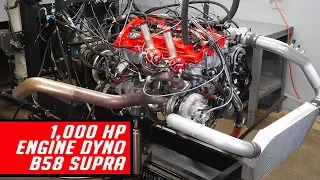
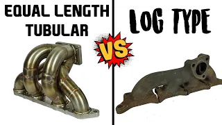
When you look inside, you can see how the puddle of solder penetrated all the way. inwards and this creates a really strong weld on all the joints and I think we ended up with a really strong head, very happy with the result although this whole process was taking a lot of time and the printer actually had some challenges and delays with Al To print the part, we were worried that the head wouldn't make it to our last event of the year at Urbandale, so Full Race also made us a head using their traditional manufacturing technique that uses straight tubes and a predefined radius. he bends and cuts them until you end up with the header you're looking for and when Full Race made the header fabricated we used Matt's Solidworks skills again and went back to the same model and instead of having a 3D printed model he made one with many segments with known curvature radii and, in fact, we designed the manifold and the entire head practically again, which is what the racing manufacturers used as a model to make the new part and we even 3D printed a plastic accessory so that they can make the collector easier and they made this whole header in less than a week so we can make sure we did the event and it's crazy that we did all this with a 3D printed header and we didn't actually finish. using it but we will use it in the future uh we just knew it's this cutting edge technology and we're a little worried about doing this and using it at the last event of the year so after adding our egts that are out of gas temperature sensors and an accessory that allows us to monitor the exhaust gas backpressure, which is the pressure between the exhaust valve and the turbine wheel.
We had the whole car running again and then it was time to start it and then put it into drive. dyno and tune it all up with our new header turbo setup so thanks for watching I hope you enjoyed it if you did hit the like button if you want to see more consider subscribing. I want to thank Solidworks again for parting ways. This whole project is software that I have been using for over eight years and it really is an industry standard in the auto aftermarket and I get asked all the time how do I get into the auto aftermarket, how do I know how to get?
I started designing things and one way is to really learn the tools of the trade and one of them is that CAD software every year Solidworks has what they call 3D world of experiences and it's an in-person conference where a group of designers and engineers get together . together and learn more about the software and designing things in CAD this year is totally virtual and in the description below I will put a vip link that you can use and attend for free and you will really use it as something for yourself. I hope you know that I'm going to use it myself and I hope that you know how to increase my knowledge and skills using CAD software, so thank you again for watching and I'll see you in the next video oh oh oh.
If you have any copyright issue, please Contact