HEAVY MACHINERY & EQUIPMENT. Giant Machines In Working. Incredible Manufacturing process
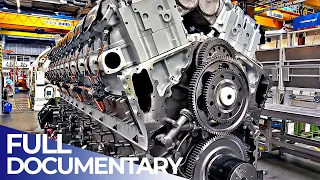
May 06, 2024Hello friends and welcome back to the Y can do television channel. The mwm TCG 2032 V16 stands as a pinnacle in the field of gas generator sets, offering a harmonious combination of energy efficiency and reliability designed to meet the demanding needs of large independent energy companies. The IP producer projects the power output, the TCG 2030 2 V16 is a powerhouse that offers an impressive power range of 3000 to 4500 KW. This wide range ensures that the engine can meet a diverse set of requirements, from industrial applications to large-scale power plants, fuel versatility. One of the most notable features of the TCG 2032 V16 is its ability to run on a large number of gas types, whether it is natural gas, landfill gas, sewage gas, mine gas or coke oven gas, this engine can handle it all, offering operators flexibility and reducing reliance on a single fuel. source High reliability and low operating costs Reliability is at the core of the TCG 2032 V6 16.

Its design and construction ensure that it operates constantly, minimizing downtime and maximizing productivity. Additionally, its optimized design ensures low operating costs, making it a cost-effective long-term solution. fast rise option that recognizes the dynamic needs of power generation mod mwm offers a fast rise option for the TCG 2032 bv16. This feature is especially crucial in today's energy landscape, where intermittent renewable sources such as wind and solar are becoming more prevalent. Rapid ramp-up ensures that the motor can switch from a start request to 100% grid load in less than 5 minutes, providing rapid response to power demands, efficiency and environmental considerations.

More Interesting Facts About,
heavy machinery equipment giant machines in working incredible manufacturing process...
The TCG 2032 V16 isn't just about raw power, it's about delivering that power efficiently. as optimized chamber spark plug ensures high fuel utilization while closed crankcase ventilation increases efficiency through the use of blown gas. Additionally, the engine design ensures soot-free combustion, reducing environmental impact and maintenance needs. Compact design and easy installation despite its power, the TCG 2032 V16. It has a compact design that guarantees easy transportation and installation. Its design considerations mean it offers up to 30% shorter length compared to some competitors, reducing logistical challenges. The Long Range Ocean Patrol Vessel POA Arm Reformer represents a pinnacle of naval engineering achieved through international collaboration at the state.

State-of-the-art shipbuilding techniques Here is a concise description of its construction
process
The Paula was conceived to allow Mexico to safeguard its vast maritime territories spanning 5 million square kilometers of sea The ship's design has its roots in the frigate Damon Sigma 10,514 a tried and tested plan that has seen multiple iterations. This 107M long ship is the tenth in her lineage, underlining the long-standing partnership between the Royal Netherlands Navy and the Dutch maritime industry. One of the most notable features of the creation of the Pola was its rapid completion from contract signing to delivery. The entireprocess
took less than 3 years.
This speed was not at the expense of quality but was a testament to great planning and execution. Efficient The rapid completion of the pole was possible thanks to the seamless collaboration between multiple stakeholders, the Mexican Navy Damon local and international subcontractors and suppliers worked together to ensure the success of the project. Their collective efforts ensured that challenges were addressed quickly and the project stayed on track. A factor that contributed significantly to the efficient construction of the vessel was the adoption of modular construction. This method involves prefabricating sections of the boat separately. which are then assembled, this approach not only accelerates the construction schedule but also ensures accuracy and quality control.
The construction process was enriched by a smooth transfer of knowledge and technology. This was critical to the success of the project, ensuring that best practices were shared and implemented across the project. It drew on the expertise of around 70 Dutch companies, including industry
giant
s such as Phy, and their combined knowledge, together with contributions from local Mexican companies, ensured that the pole was built to the highest standards on the cool morning of the October 20. The Majestic MC magnifica extends for almost 300 meters. M sailed towards the port of Rotterdam, her destination was berth number 8 at Damon Ship Repair roddam, one of the largest berths in Western Europe, as soon as safety protocols allowed, repair work began on Earnest Crews quickly Tools were lowered, scaffolding erected and steel workers prepared for a major task that replaced a whopping 40 tonnes of steel.Simultaneously another team embarked on a monumental painting job with over 6,000 square meters of room surface required. attention there was no room for delay the stern of the ship also witnessed a flurry of activity the old rudder systems were dismantled and the rudder stocks were transported to an on-site workshop, here they underwent modifications to perfectly fit the new rudders. This proximity of the facilities was a testament to the shipyard's efficiency, ensuring Swift's repair operations while primary repair tasks were in full swing, another team diligently tending to the lifeboats and davits the ship began to transform. new paint made it shine Under the sun welders expertly installed new steel plates and the rudder bearings after meticulous measurements were ready for the modified rudder stock, these bearings were cooled with nitrogen to ensure a perfect fit in the linkage system The MSC magnifica anchor chains integral to the ship's anchoring system were meticulously inspected for signs of wear, corrosion or damage.
Simultaneously, the ship's stabilizers and thrusters underwent extensive examination. Stabilizers similar to submarines. The wings counteract the role of the ship by ensuring passengers comfort even in turbulent conditions. and Waters, the thrusters, on the other hand, provide the ship with improved maneuverability, especially crucial during docking or sailing in confined spaces, minor repairs to these components were quickly addressed as the magnificent rejuvenation process approached its completion. culmination. A new coat of antifouling paint was applied. Hull, this specialized paint serves a dual purpose: it not only gives the boat a fresh look, but also prevents marine organisms on land from sticking to the boat, reducing drag and improving fuel efficiency.
Lastly, the ship's propellers, the heart of her propulsion system, were polished and this polishing process not only restored her shine but also optimized her hydrodynamic efficiency. Hamburg's Prime service stands as the most important hub within the Prime Set network. In this part, you can do TV and it will show you the intricate area of repairing and overhauling engines and parts. The workshop tour reveals the depth of technical expertise available. A fundamental step in the process is spoke grinding, crucial for the optimal
manufacturing
of the crankshafts. Within the facilities is a state-of-the-art machining center dedicated to repair and reconditioning tasks.In particular, the type 3240 cooling jacket undergoes restoration here. A testament to modern engineering, the 5 AIS machining center has capabilities for drilling, milling and turning complex components, including two-stroke piston crowns and, in certain cases, counterwaves. Experience also covers complete overhaul and repair of diesel engines Precision is evident in the assembly of a type 5.255 cylinder block Integration of laser welding characterized by load Distortion and precise material arrangement offers an environmentally friendly solution that prioritizes operator safety this method is invaluable for applications requiring localized repairs a significant The operations segment focuses on the repair and
manufacturing
of service crankshafts.There, crankshaft journals and journals undergo reductions tailored to specific demands, such as the creation of custom cooling tubes. Specialized tools make it easy to grind even the most compromised crankshafts without removing them from the engine. The emphasis on quality assurance is evident with rigorous crack testing and a variety of welding techniques ensuring top-notch results at competitive prices, aligned with customer expectations. This provides an initial view of the expanded repair. TX's task focuses on replacing a crankshaft. The images capture the preliminary phase. Of the repair that involves the removal of the cylinder heads and the lifting of the pistons given their weight, the handling of the cylinder heads and pistons poses challenges especially due to the possible rocking during lifting, it is imperative to use tools designed for hydraulic nuts with precision prioritizing the safety of all personnel. involved in the operation, the second step of a large repair job involves the removal of coatings that can be quite
heavy
.It is important to be careful during this step and take the necessary safety precautions to avoid any potential risk of injury. Lifting
heavy
loads requires adequate technique and physical strength so it is advisable to work in teams to distribute the weight evenly, it is important to avoid sudden movements or jerks that may cause the liners to fall or move, causing potential damage to the time. To lift and protect the range gears during a major repair job it is essential to handle them carefully to avoid any damage or damage to their fragile and sensitive parts as demonstrated in the video.The recommended approach is to use adequate protection around the
equipment
to ensure optimal conditions for lifting and transport. This protection may include items such as foam padding or sturdy cases to keepequipment
safe and prevent accidental impacts. By taking these precautions, range equipment can be moved safely without any risk of damage, ensuring that repair work can be completed effectively and efficiently in the process of transporting and preparing a new crankshaft for shipment. Installation on a boat engine, it is important to note that the crankshaft is coated with preservative oil at the factory to prevent rust during storage and transportation;However, before installation it is essential to remove and clean the preservative oil. oil, which can be a time-consuming process, the crankshaft is one of the heaviest parts of the engine, so special lifting equipment will be needed to safely lift and install it when lifting an A-frame is part of a large repair job, it is crucial to use sufficient labor to ensure the process is efficient and safe. Underestimating the number of workers needed for the job can create potential risks and hazards, so it is important to prioritize safety using a adequate number of workers for the task lifting a crankshaft can be a challenging task due to its considerable weight, as shown in the video, it is essential to use sufficient manpower and special lifting equipment to ensure safe and efficient lifting of the crankshaft from the base plate to the transport cradle.
It is essential to take the necessary precautions. During the lifting process to avoid potential risks or dangers once the crankshaft is lifted, it is necessary to transport it using a special base to ensure it moves safely. Curious about engine overhauls and crankshaft installations? Watch this video and see how. A new crankshaft is transported from the service shop to the boat where it is installed in the A-frame. Remember that the main bearing bolts are sensitive and should not be damaged during the installation of a new crankshaft, so we recommend protecting the main bearing bolts. main bearing properly. and being careful not to damage them in a large repair job, installing new pistons and liners is a crucial step in restoring proper engine operation, as shown in the video.
It is important to pay close attention to the O-rings when installing new ones. Pistons – These rings play a vital role in securing the pistons and liners in place and any errors during the installation process can lead to major problems, so it isIt is essential to ensure that the O-rings are installed correctly to avoid possible leaks or malfunctions that this requires. Careful attention to detail and precise positioning of rings during installation. By taking the time to install O-rings correctly, new pistons and liners can be properly secured contributing to the overall effectiveness and longevity of the engine. Proper alignment is essential when installing a turbocharger. rotor during a large repair job as demonstrated in the video, it is essential to take care during the installation process to ensure the rotor is aligned correctly.
Any misalignment can cause serious problems, including engine damage and decreased performance, so it is essential to pay. Pay close attention to the alignment of the TC rotor during installation to ensure it is mounted correctly and will function properly in the ever-evolving manufacturing landscape. The integration of cutting-edge technology has become synonymous with innovation and efficiency. At the heart of this transformation are Marshall trailers. A company that has embraced the future by investing £1 million in SAP factory management software, revolutionizing its production process and ushering in a new era of control and precision from a trailer manufacturing process perspective, this change marks a pivotal moment when technology merges seamlessly with craftsmanship to redefine the art of production Entering Marshall Trailers Factory today reveals a scene of orchestrated efficiency Guided by the watchful eye of SAP software, this same software has proven its worth in the management of industry
giant
s such as John Deere New Holland and Claus in the agricultural sector. solidifying its position as the gold standard in process management as the trailer hits the road The manufacturing process gets underway Sap's pervasive influence becomes palpable from the inception of an order to final delivery, no facet escapes his meticulous supervision, drawing inspiration from the meticulous methodologies of the Marshall automotive industry.The technological metamorphosis of the trailer is evident in the details. The impact of the software is felt in numerous areas, starting with planning, where it orchestrates a symphony of variables, from personnel assignment to the acquisition of raw materials to choreographing an impeccable production routine with Sap's Adept management
machines
with Newfound, precision cutting, bending and robotic welding brake presses are guided by an invisible hand that ensures accuracy down to the smallest fraction of the measurement in the At the heart of the Marshall Trailers Factory, one faces the vision of a sap-controlled bandsaw operating within the realm of the Red Zone, a testament to the trust placed in this intelligence system.Nearby welding robots dance in precision choreography, their every move calibrated by SAP algorithms, the convergence of human expertise and the digital domain, resulting in welds that are not only strong but visually flawless. However, Sap's mastery does not end with the
machinery
, it extends to the environment itself, the software silently manipulates the climate within the factory by regulating temperature and humidity. to create the perfect conditions for the trailer painting process at the newly established shot blasting and paint spraying facilities. Sap's orchestration is evident when timing the nanc application process. This meticulous control ensures that every trailer that leaves the factory has a consistent, long-lasting finish.Seal of quality and attention to detail beyond the factory. Sap's influence permeates every corner of the Marshall trailer operation. The software takes over the intricate ballet that is inventory management with over 8,000 parts manufactured and an additional 10,000 purchased in components to ensure that Sap's prowess shines as it ensures the right part is in the right place at the right time this Harmonizing inventory management eliminates bottlenecks and keeps the production process flowing smoothly The true testament to Sap's impact however lies in the very essence of Marshall Trailers products with its guidance the company has embarked on a Journey towards consistently producing high-quality trailers with each passing batch.
A shining example is a line of identical VES rear discharge spreaders produced flawlessly as planned and ready for their designated destinations. This level of consistency and precision would not be possible without guidance. hand of sap fully automatic anchor bolt production line is characterized by its integration of CNC operated
machinery
automation and advanced processes. The process begins with the automatic material feeding machine that supplies the raw materials needed for the production of anchor bolts. Follow the 360° raw material straightening machine. meticulously aligning the materials for optimal processing the aggregate conveyor system takes over the transport of the straightened raw materials to the subsequent stages of production here the alligator type hydraulic cutting machine intervenes by precisely cutting the materials to the desired lengths consistently meeting the required specifications continuing along the line The numerically controlled Czer comes into play by shaping raw materials into anchor bolts of precise dimensions.Hydraulic bevel angle cutting improves the structural integrity of the bolts and ensures a secure fit in their intended applications as the anchor bolts advance and enter automatic production number one. line a crucial phase that houses specialized
machines
dedicated to various tasks the combined type hydraulic neck machine operates in conjunction with the hydraulic thread rolling machine to create the distinctive features necessary for secure anchoring that guarantees the quality of each component a nut screen extracts perfectly formed nuts ensuring a flawless final product, the automatic combination nut screw machine expertly assembles nuts onto bolts achieving perfect integration. Of particular note is the integration of a shock-absorbing nut bolt designed to absorb vibrations and contribute to the longevity of the structures.A key player in the line is the fully automatic punching and punching machine, a high-precision device that improves the structural integrity and functionality of anchor bolts. The bolts emerge from this stage with greater strength and usefulness, ready for the next phase of production. The journey concludes with meticulous attention to packaging and distribution a strapping and finishing machine organizes and packages the anchor bolts ensuring their presentation and protection during transport the automatic steel strapping machine is responsible for securely tying the anchor bolts in packages that are ready for shipment even the final steps are executed with the same level of automation the CNC stacking crane effortlessly handles the loading process by efficiently moving packaged anchor bolts to designated storage or shipping areas the hydraulic alligator cutting machine takes over to precisely cut raw materials into specific lengths numerical control comes into play with the sizing process where a combined hydraulic neck machine is used to shape the anchor bolt heads while a rolling machine Hydraulic threading imparts the necessary threads to the shaft, the production line incorporates innovative technologies such as a combined spinning and impact machine, extrusion, cold rolling mill and automatic spot welding machine.
These machines work together seamlessly to create anchor bolts with superior strength and precision. The torque machine adds the finishing touches to the anchor bolt design improving its performance characteristics. The automatic combination nut screwing machine adds versatility to the production line, allowing the joining of multiple nuts. Anchor bolt configurations to ensure durability and aesthetic appeal of anchor bolts. The production line includes processes such as fully automatic punching and fixing. After these processes, the anchor bolts can pass through a painting and drying room where protective coatings are applied and cured to improve corrosion. resistance After going through the painting and drying stage, the anchor bolts go to the strapping and finishing machine.
This machine speeds up the packaging process by efficiently grouping the anchor bolts for transport and distribution. An automatic steel strapping machine secures the packages. finished ensuring they remain intact during handling in transit, the incorporation of automation into the production process is further highlighted with the inclusion of a CNC stacking crane. This advanced crane system handles the movement and storage of raw materials and finished products within production facilities, improving efficiency and minimizing the need for labor. A heavy duty front lathe machine designed to process rotor shafts and axles with a load capacity of 120 tons is a complex and intricate process involving precision engineering and advanced control systems.
Here is an overview of how this impressive machine works Setting up the load The process begins with positioning The huge spindle or rotor shaft on the lathe bed, this is a critical step as the workpiece must be held securely to withstand the intense forces and vibrations during machining. Hydraulic or mechanical clamping systems are often employed to ensure stable grip of the tools on the workpiece and Definition of the tool path Appropriate cutting tools are selected based on the specific requirements of the workpiece. These tools are mounted on the lathe tool turret or post. The operator then defines the tool path by specifying the desired dimensions, surface finish, and other machining parameters.
Precision machining of lathe machine. It begins rotating the workpiece at a controlled speed while the cutting tools move along the workpiece removing material with high precision. The heavy-duty nature of the machine allows it to handle large workpieces without compromising the precision of cutting operations depending on rotor design and specifications. shaft or spindle several cutting operations are performed these operations may include turning threaded facing grooving and tapering lathes the tool turret can hold multiple tools allowing sequential operations without the need for manual intervention control systems and measurements modern lathe machines Heavy duty front end machines are equipped with advanced control systems that ensure consistent and precise machining, these systems often incorporate CNC computer numerical control technology that allows programmable control of the machining process.
Precise measurements are taken during machining using sensors and probes to ensure the workpiece adheres to the specified dimensions. Surface finishing achieving the desired surface finish. It is crucial in applications such as Sha rotor and shafts where smoothness and precision are paramount. Lathe machine cutting tools combined with appropriate feeds and speeds create the required surface texture and geometry. The aluminum extrusion process is a highly versatile method used to create complex shapes with aluminum alloys. for various industrial applications 16 inch billet cutting machine, this machine accurately cuts aluminum billets to the required length, ensuring consistency in starting materials. This process involves pushing or pulling heated aluminum billets through a molded dye to produce profiles with consistent cross sections.
Mold preheating oven, a crucial element. step to ensure molds are at the optimal temperature for extrusion, improving product quality 6000 t semi-extrusion and seamless machine capable of handling extrusions with cross sections of up to 500 mm. This machine ensures smooth and seamless production. 450 t stretching machine. This machine allows the stretching of extruded products. aluminum profiles that improve their mechanical properties and dimensional accuracy 13.5 M aging Heat treatment oven aging Heat treatment improves the strength and durability of aluminum profiles, making them suitable for various applications anodizing plant with an internal anodizing plant, the installation can provide corrosion resistant profiles and aesthetically pleasing finishes.
Multi-axis straightening machine ensures that extruded profiles maintain aprecise and critical dimensional accuracy for the functionality of the final product. 45° double blade angle saw. This machine offers speed and angular size. Precision when cutting profiles, optimizing production efficiency. Electric automatic cutting machine. The machine not only provides accurate length and size, but also flattens the cutting surface meeting high quality standards. Integrated manufacturing and quality control. The manufacturing process is characterized by its integration with each step optimized for a seamless transition to the next. This integration combined with professional equipment ensures that products meet the desired specifications and quality standards.
The facility's commitment to quality control is unwavering, resulting in products that consistently meet or exceed customer expectations and the facility's capabilities. extend to a variety of CNC machines allowing customization and versatility in aluminum extrusion profiles. Additionally, the facility offers a variety of painting options including liquid powder and fluorocarbon coatings that meet different aesthetic and functional requirements the production cycle. bolts begins with the preparation of raw materials input materials are thoroughly inspected and blanks of required size are cut using automated band saw machines the process ensures precision cutting required for high quality end products stamping process in Hot The hot stamping process involves heating the workpieces using high frequency current.
The inductor powered by high-tech generators based on new generation transistors heats the workpieces quickly and accurately up to a temperature of 1100° C temperature control is managed by a built-in infrared pyrometer, depending on the product, bolts or nuts, the entire workpiece or specific parts are heated, molded and shaped after heating, the workpiece is placed into a mold and subjected to an impact press. The molding process can take place in several stages with the aim of achieving the desired shape with minimal mechanical processing, automatic marking of blanks is carried out after shaping the bolt head. Threading is a crucial step in bolt production.
Bolts are produced using automated threading machines with tangential cutters. Threading is verified using gauges to ensure accuracy. Internal threading of nuts is carried out using semi-automatic milling machines with automatic reverse galvanizing. Corrosion protection is vital for hardware products. Two galvanizing methods are used. Hot dip galvanizing in electrochemical galvanizing. Blanks are prepared for galvanizing through a series of steps including washing, degreasing, acid etching and Rinsing the main protective layer is applied during the galvanizing process, which involves dipping at high temperatures, excess Zinc is removed by centrifugation and passivation is performed for standardized protection. During hot dip galvanizing, bolts are subjected to a high temperature zinc bath, resulting in the creation of a robust zinc layer on the surface, this layer not only provides a formidable shield against corrosion, but also gives the bolts greater durability and a uniform protective layer.
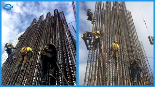
In contrast, electrochemical galvanizing involves immersing bolts in an electrolyte solution containing zinc ions by applying an electric current. Deposited on the surface of the bolt forming a thin but effective layer of zinc, this layer acts as a barrier that prevents corrosive agents from attacking the metal. Final processing The manufacturing process ends with the final processing of nuts and bolts. This includes calibration of internal and external threads using specialized taps and taps. tools to prevent damage to the zinc layer the high-atmosphere oil and gas field located in the Danish sector of the North Sea represents a significant development in the region's energy landscape the process of installing this field is a testament to the intricate engineering skill of planning and collaboration Thanks to the efforts of multiple stakeholders, the journey began when the tall jacket, a colossal 8,400-ton steel structure designed to support the tall platform, was loaded onto barge H 627 in Bingham, Netherlands.
This jacket would serve as the fundamental structure for the platform, ensuring its stability amid the challenging conditions of the North Sea while preparations were carried out. The submersible crane vessel S SSCV Hermod was mobilized from the port of Roddan this vessel equipped with crane capabilities advanced would play a critical role in the installation process upon reaching altitude, a place where the hermod faced its first challenge deploying anchors in adverse weather conditions despite the turbulence the forecast was promising and the team pressed ch in a coordinated maneuver The barge carrying the high air jacket met the hermod at the high airfield the high airfield located in the North Sea was first introduced to the energy industry in 2001 with the drilling of the hj1 well, this exploratory well was drilled using the enco 101 jackup Rd and reached an impressive depth of 5265 M.
This initial drilling was instrumental in identifying the potential of the elevated air field with C-holding was precisely cut and simultaneously the barge was trimmed with ballast to ensure the stability. A few years later, in 2005, further exploration was carried out with the drilling of the hj2 well. Once again the enco 101 jack-up equipment was used, this time reaching an even greater depth. of 5,399 M, the results of this drilling activity were promising as they not only confirmed the presence of oil but also showed the potential of the field. The culmination of these efforts was the release of the jacket into the North Sea on a Friday afternoon.
This process took less than a minute. The bar's ballast tanks filled with water, causing a slight tilt and allowing the massive steel structure to glide gracefully into the sea. Floating tanks and cleverly designed compartments within the jacket ensured that it remained floating after launch. The next phase was the dumping operation. Ballast hoses were connected and water was methodically distributed to individual compartments in a predefined sequence. This control process slowly brought the jacket to a vertical position with the jacket upright, the Hermods crane taking charge of meticulously placing the jacket in its exact location on the seabed.
One of these efforts was the landing that marked a major milestone in the process of installing High Wind Scotland, the world's first floating wind farm on the vast expanse off the coast of Scotland. A revolutionary idea has come to life 16 years after its conception in a simple napkin the world now witnesses strong winds Scotland, the world's first floating wind farm, this monumental achievement is a testament to human ingenuity and the relentless pursuit of sustainable energy solutions. The journey began with a demonstration version built off the west coast of Norway with the aim of testing the floating wind concept. turbines Despite skepticism, the demonstration exceeded expectations and produced valuable data that further refined the strong wind concept.
This innovation is a perfect combination of long-standing offshore operational experience and the need to harness wind energy in deeper waters. The strong wind Scotland is more than just a test of The concept is a functional wind farm with five enormous turbines that, seen from the coast, seem to touch the horizon invisible to the eye. A network of cables connects these turbines and transmits the generated electricity back to the mainland. This colossal project can power up to 20,000 UK homes the turbines are anchored to the seabed using huge suction anchors each weighing approximately 111 tonnes these anchors along with the turbines were a collaborative effort between Scottish and Norwegian companies showing the international cooperation in the field of sustainable energy the floating substructure the heart of strong winds Its design distinguishes it from traditional bottom-fixed turbines with a length of more than 90 M and a weight of approximately 3,500 tons.
These substructures were meticulously designed by Nantia in Spain. The turbines themselves underwent an evolution that grew from 2.3 to 6 megaw since the initial demonstration. A significant innovation within the Strong Wind concept is the motion controller. This ingenious system tilts the blades to stabilize the floating structure, optimizing energy production even in difficult conditions. However, the journey was not without its challenges, from managing multiple contracts to executing heavy lifting operations. The project required precision and collaboration. One of the most daunting tasks was lifting the fully assembled turbine onto the floating substructure. By August, all five turbines were operating at full speed.
This pilot project not only pushes the boundaries of offshore wind technology, but also paves the way for larger projects in new areas. areas Impressively, the cost per megawatt for the Scotland High Winds project has been reduced by 60% compared to the initial demonstration in the field of marine projects The transportation of massive components is a critical and challenging task the large size and weight of these components such as the 590 t marine tripod or the 212 t vertical tower segment require specialized equipment that can handle their magnitude while ensuring safety and efficiency. Enter the spmt self-propelled modular transporter, a game changer in the world of heavy lifting and transportation.
SPMTs are multi-axle platforms fitted with a wide variety of wheels, these platforms can be combined in various configurations, allowing them to carry exceptionally heavy loads. Its design is inherently modular, meaning multiple MTS SPs can be joined together, side-by-side and end-to-end, to form larger platforms. This modularity is essential when dealing with large offshore components, as it provides the flexibility to adapt the size and shape of the Transporter to the specific needs of each cargo, one of the most notable features of SPMT is its ability to distribute the weight of the load between its axles evenly. This weight distribution is crucial when transporting massive components such as the 590t marine tripod, by ensuring the weight is distributed, spms reduce the risk of structural damage to roads or other infrastructure and ensure load stability during transit .
The 212 t vertical tower segment, another colossal component in marine projects. You also benefit from the precision and control that SPMS offers. These conveyors are equipped with advanced hydraulic systems that allow for precise height adjustments. This feature is invaluable when dealing with tall vertical components, as it ensures that they remain stable and upright throughout the transportation process. They come with computer controlled steering. This feature allows for synchronized movement of the wheels, ensuring the transporter can navigate tight spaces. Make sharp turns and even move sideways if necessary. Such maneuverability is essential in complex port, shipyard or construction site environments where space is often limited. and accuracy is paramount, in addition to their technical capabilities, spmts also play a critical role in project schedules.
Its efficiency and reliability mean jumbo-sized components can be transported more quickly and safely, reducing delays and associated project costs. The marine energy sector has witnessed numerous engineering marvels. over the decades, but few stand out as prominently as the vemon jacket built by the Hira manufacturing group to withstand this colossal structure weighing a staggering 9,150 tons is not only a testament to Lenin's capabilities, but also highlights advances in marine engineering and the Potential of the North Sea The North Sea, with its vast reserves and challenging conditions, has been a center for offshore innovations. The Vemon field located between Kavite Bjorn and Gfax South Fields is one of those reservoirs that required robust and advanced infrastructure to harness its potential.
Enter HMA Manufacturing Group, a renowned name in the offshore construction sector, tasked with building the largest jacket ever built at its blissing and yard for the design of the Stoyles Vemon field and its initial phases. The journey of the Vemon jacket beganwith meticulous planning and design given the challenging conditions of the North Sea. The jacket had to be robust, durable and efficient. In the initial phase the first cut of steel was made in Lingan Herum, which marked the beginning of the project. This fundamental step is crucial as it sets the tone for the entire build, ensuring precision and quality from the beginning.
Construction Milestones The construction process was marked by several important milestones. The rolling process, which involves bending or bending large steel plates to form the cylindrical section of the casing, was executed in multiple phases. The top. Row one was the first to undergo this, followed by the bottom and then the top of row five, these rolls ensured the vertical assembly of the jacket providing the necessary height and structural integrity. J-pipes and risers essential for oil and gas transportation. The J-pipes and risers were precision manufactured. These components guide and protect the flow lines and umbilicals from the seabed to the top of the platform.
The wellhead module controls the extraction process. This 210 metric ton module designed by HFG Engineering and built by Herum of Lingan ensures the jacket remains firm even in the harshest conditions. safe and efficient, loading and transporting with the jacket and its components ready the next challenge was its transport to the North Sea The loading operation, a major logistical feat, involved loading the enormous structure onto a barge, given the size and weight of jacket, this operation required state-of-the-art equipment, precision and coordination, navigation to its destination on the high seas marked the culmination of months of hard work. Navigating through open water with such a colossal structure required detailed planning, expert navigation skills and a deep knowledge of North Sea conditions.
Installation and operations upon arrival at your destination. The Vemon jacket was anchored to the seabed providing a stable base for the Vemon platform. The installation process. carried out in a water depth of around 135 M it was a major engineering challenge the jacket serves as the base for the vemon platform equipped to treat gas and condensate from nearby discoveries the operations of the platform are a testament to the design and Robust jacket construction ensuring efficient extraction and transportation of resources, the Vemon oil and gas field, located in the North Sea, is a testament to advanced offshore engineering and the potential of the hydrocarbon reserves of the region, located between the Cavite Bjorn and Gfax South fields, approximately 160 km west of Bergen, the field has been a major contributor to the energy sector since its discovery Discovery and development Lemon was discovered in 1985 and has since been a hotspot focal point for energy extraction in the North Sea.
Production began on January 3, 2015, marking a major milestone in its development. Trip the field development consists of a remotely operated fixed jacket platform equipped with an aerodynamic separation facility for gas and water condensate. This advanced platform is designed for remote control from an operations center located at Sandley in Bergen, showcasing the integration of technology into modern offshore operations. Complexity of the deposit. The Vemon deposit is located at a depth of around 4,000 M and is known for its complexity. The reservoir is not only fractured but also characterized by high pressure and high temperatures. Despite these challenges, the field has contributed significantly to the energy sector, however, recoverable volumes have been reviewed over time and the plan for 2021 estimates a recovery of around 18 million M3 of gas, 0.2 million M3 of NGL and 2.3 million M3 of condensate.
Transportation and infrastructure. Condensate extracted from Vemon is transported via a gas pipeline to the Kavite Bjorn platform. for post-stabilization, it is subsequently transported to the Mongstad refinery located in Hordaland. Gas from Vemon has a two-phase transportation plan until 2023. The gas is headed to Heimall after 2023. The gas will be transported together with condensate for separation at Kite. DN gas is then processed at KES north of Bergen before being routed to European gas markets. An additional feature of the Vemon field is its electricity supply which comes from Kavite Bjorn via an undersea cable. Recent discoveries in a major development effort announced a new gas discovery near the Vemon field called Vemon West 2 years after Vemon began operations, this discovery is estimated to contain between 20 and 50 million barrels of oil equivalent.
Gunner Nacken Statoil's West Group Senior Vice President of Operations emphasized the importance of this discovery for the further development of lemon, highlighting the opportunities that still exist in the North Sea and the potential value that these reserves can bring. Installation of the Vemate offshore wind farm. The Vemate offshore wind farm is a testament to the wonders of modern engineering and the potential of renewable energy. Located approximately 130 km north of Haven in the German section of the North Sea, this wind farm has a capacity of 400 megawatts, enough to power 400,000 homes in Germany. The wind farm is located about 95 km northwest of Borham Island, in Germany's exclusive economic zone. area an area recognized for its strong and constant winds with water depths ranging between 39 and 41 M the installation of the wind farm presented unique challenges the scope of the project encompassed the design, procurement, manufacturing, transportation and installation of the foundations for 67 wind turbines, these foundations consisted of huge monopiles and transition pieces.
The monopiles designed and manufactured in Rostock, Germany, are truly colossal, they are the largest in the world with an astonishing length of up to 85 m, a diameter of 7, 8 m and a weight of up to 1,300 tons. The transition pieces, each weighing 350 tonnes, were manufactured in Alard Denmark. Both components were then transported to a marshalling yard in E Haven, Netherlands in preparation for installation. The installation process was led by the Skyla cjack a vessel. of new generation jack-up installation equipped with a crane capable of handling 1,500 tons this vessel was responsible for installing the monopiles while the cjack zaran transported and installed the transition pieces the installation strategy involved transporting three monopiles at a time on the Skyla and six transition pieces at a time in the zaran ensuring that the project was developed in sequence an important aspect of the installation was the scour protection executed using the bosal drop vessel.
Rock Piper, this process was initiated after thorough detection and removal of unexploded ordnance throughout the site. Noise mitigation was another crucial component of the project, given the strict underwater noise requirements in Germany, to meet these requirements boscus employed a hydraulic sound dampener in the gripper frame and a double bubble curtain which ensures that the Noise levels are kept within agreed limits. The V project was completed in the fall of 2016. The wind farm is expected to be fully operational by the end of 2017. This effort shows the experience in epci project management and offshore wind turbine foundation installation the success of the project vamate is a testament to the dedication Innovation and resilience of all the teams involved Paving the way for future offshore wind projects the tricolor a car carrier owned by the Norwegian shipping company will wilhelmson and operated by wellenius wilhelmson Logistics met a tragic fate The Ship loaded with more than 2,800 new cars destined for the US market was hit by the container ship KBA, causing it to capsize within half an hour.
This event set the stage for one of the most complex and extensive. Salvage operations in maritime history The collision with the Kuba caused the tricolor to sink quickly and rest on its port side at the bottom of the channel. Fortunately, the 24 crew members of the ship were able to evacuate in time, avoiding any loss of life caused by the tricolor. sunken. a significant threat to one of the world's busiest shipping routes, in addition, it began leaking fuel oil the owner's priority was to minimize environmental damage the Asian Hercules 2 a floating cutting leg was sent to the site to serve as a stable platform for the rescue team divers. sent to inspect the vessel and begin the process of removing the oil trapped inside the tricolor.
Timing was not only a logistical challenge but also an environmental concern, primarily due to the large amount of oil on board the vessel's position resting on its conventionally made side. Oil disposal methods were not practical to address this problem. The salvage team had to innovate by recognizing that the orientation of the vessel provided access to the bottom of the oil tanks. They decided to tackle the problem from below using specialized drilling equipment. They drilled into the tanks creating access points to ensure that the oil could be safely extracted without spills. The valves were meticulously placed in these holes.
These valves acted as controlled gates that allowed oil to be pumped systematically over an intensive two-month period. The team worked tirelessly extracting oil and transferring it to separate containment units. Their efforts were commendable in successfully removing most of the 2,100 tons of oil on board; However, the complex structure of the tricolors meant that some oil deposits remained inaccessible despite the team's best efforts, some of this trapped oil inevitably found its way to the sea, underscoring the challenges and limitations of such oil operations. Salvage, once the immediate environmental threat of oil was addressed, attention turned to the colossal task of removing the tricolor wreck, recognizing the scale and complexity of the operation, the ship's owners sought the expertise of the leaders of the industry and hired a consortium that brought together the specialized skills of several companies Smith Salvage and molr ship from the Netherlands and scaldis and orse from Belgium this collaboration ensured a combination of resources of experience and innovative techniques given the tricolor size and risks potentials of raising such a massive structure intact, a strategic decision was made the ship would be segmented the plan was to cut the tricolor into nine sizable sections, each of which could be handled more safely and efficiently than attempting to save the ship as a whole.
The process of segmenting a ship of tricolor magnitude was unprecedented and required precision cutting tools, underwater experience and a coordinated effort between teams above and below water, each section once separated was then individually lifted and transported for later dismantling and recycling. Two critical phases of this operation were the cutting of the sunken ship into manageable sections and the subsequent lifting of these sections for transportation and scrapping. The cutting process set the stage to begin the cutting process. Two enormous work platforms were strategically assembled on each side of the ship. submerged tricolor shipwreck these platforms were not simply ordinary structures, they were specially designed to provide stability in the challenging underwater environment and to support the heavy machinery and equipment required for the operation the special cutting wire the main tool for this operation was a cutting wire unique cut that had previously proven effective in the rescue of the Russian submarine KK this wire was not a simple thread but a sophisticated piece of engineering was composed of a series of small cylinders hung on a steel wire.
These cylinders were coated with a material known as wedia, a mixture of special types of steel that approached the hardness of diamonds, which ensured that the wire could cut the tricolor steel structure with precision by maneuvering the wire to place this wire. cut under the tricolor. A flexible drill was used. This drill was designed to penetrate the seabed, navigate beneath the wreck, and emerge on the other side once the drill had created a path. The hollow tube was removed creating a conduit for the cutting wire, the wire was then passed through this tube,placing it under the container and setting the stage for the cutting operation.
The cutting operation with the wire in place began the real challenge, the wire was pulled. taut and then moved back and forth between the two platforms effectively acting as a saw. This cutting action powered by large winches on the platforms methodically cut the tricolor into nine distinct sections. The precision and effectiveness of this method were evident in the even clean cuts achieved. Across the ship's multiple decks and engine room, the lifting process, each section of the tricolor presented its unique challenges. The ship had been cut into nine distinct sections, each varying in weight and structural integrity.
The process began with clear legs placed strategically around a section. Multiple cables attached to the section were then connected to the cutting legs as lifting began. The first site was often the lifting frames that had been previously welded to the sections to facilitate the process. These frames were crucial, especially given the weakened state of the vessel afterwards. months under water and the cutting process, the lifting was deliberately slow, this was not only to control the immense weight but also to allow the water trapped within the sections to drain properly. A quick lift could have caused a sudden change in weight, which could have had catastrophic consequences, in addition to the even weight distribution between the two steep legs was paramount.
Any imbalance could strain the equipment and jeopardize the entire operation. The challenges and precision of the tricolor structure had been compromised not only by the sinking but also by the shearing process and the natural forces it was subjected to while submerged, this meant that each section, while massive, was also fragile, sharp legs, although powerful, had to be operated on by a surgeon. Precision divers played a crucial role during this phase, continually monitoring the sections as they were raised, ensuring that the cables held firm and that the sections did not break. Their feedback transmitted in real time to the surface team was invaluable in making on-the-spot decisions.
Section suspended slowly with the transparent legs controlling the descent, the section was placed on the barge. This process, like the survey, required absolute precision. The barge had to be stabilized to ensure it could support the weight of the section without tipping, once the massive sections of the tricolor were safely lifted and placed on barges they were transported to a specialist zebra facility in Belgium this facility was specifically prepared To handle the scrapping of such a large vessel and its cargo, the scrapping site at Zebra was meticulously prepared to ensure an environmentally responsible dismantling process. The foundations of the site were covered with layers of plastic covered with metal plates.
This configuration ensured that any residual oil or contaminants from the tricolor would not seep into the ground, preventing environmental contamination. The process of breaking the sections of the tricolor was a huge task. Thousands of tons of steel had to be cut, separated and processed for recycling. Specialized equipment and trained personnel worked diligently to dismantle the vessel, ensuring each piece was accounted for and processed properly. The tricolor cargo made up of more than 2,800 luxury cars was a tragic spectacle at this time. Vehicles that were once symbols of luxury and engineering prowess were now mangled and corroded from their time underwater.
Each car was carefully removed and a strict regime was implemented for its disposal. Manufacturers required a disposal certificate for each vehicle, ensuring that the cars were scrapped responsibly and in accordance with environmental standards, after the primary sections of the tricolor were removed, the salvage team's attention turned to the parts. smaller pieces that had been scattered during the sinking and subsequent operations using an advanced magnetometer in multibeam systems, the team meticulously scans the seafloor to locate each fragment. No matter how small divers were sent to recover these remains, given the vast area to be covered and the various sizes of the debris, this was a challenging and time-consuming task.
Cars, ship parts and even smaller metal fragments had to be located and lifted into place. surface the challenge was not only in the recovery but also in ensuring that the marine environment was not further altered in the process the commitment to leaving the seabed as clean as possible was paramount each recovered piece was a step towards fulfilling this commitment The French and Belgian authorities closely monitored the cleanup process ensuring that the Salvage team met the highest environmental standards. Gemini's Railways Gr 7s Wheelset is a state-of-the-art horizontal lathe designed to provide exceptional power and precision in machining wheelset axles and loose wheels for railway applications.
The winch is renowned for its versatility and accommodates a wide range of wheel sizes, weights and axle lengths, making it a one-stop solution for various railway maintenance needs. One of the notable features of the gr 7s is its high-power cutting capacity that ensures efficient and precise machining of wheel sets with a maximum tread diameter of 840 to 1250 mm and a track width of 1435 mm, the winch accommodates different wheel specifications commonly found on railway systems. It can handle wheel set weights of up to 5,000 kg or 8,000 kg and axle lengths range from 3,000 mm to 4,000 mm, highlighting its flexibility to adapt to various railway equipment.
The lathe design emphasizes production quality with impressive precision specifications. Radial runout is kept at an impressive 0.10mm, ensuring finished wheelsets have minimal imperfections. profile accuracy and difference. The diameters between the wheels are also kept at a high standard of 0.15mm and 0.10mm respectively, the surface roughness is kept at a remarkable 0.012mm, demonstrating the lathe's ability to produce smooth and contoured components. fine finishes. The gr 7s is equipped with advanced technologies to improve its performance and ease of use, customized interfaces streamline operation, while automatic measurement systems contribute to precise and consistent machining. The HT series SOP heavy duty CNC lathe stands out as a reliable and robust solution for medium-sized machining tasks, crafted with precision and durability in mind, these lathes feature construction where the main components are made of cast iron, ensuring rigidity and long life, a notable feature of HT lathes is their unique bed design.
In the ht6 and ht12 models, the bench incorporates three guides, including a divided central guide. This innovative arrangement facilitates the smooth movement of the carriage along the tailstock side which allows the passage of various accessories such as steady rests. In the case of the HT22 model, the platform has four guides that further improve stability and precision during machining operations. The HT series of lathes are designed to tackle important workpieces. With an impressive capacity to support loads of up to 22 tonnes between centres, these lathes are equipped to handle workpieces with diameters up to 2000mm and lengths in excess of 3m, allowing which makes them versatile tools suitable for a variety of applications.
Customization is a hallmark of HT. Series of lathes that can be equipped with different turning units adapted to specific requirements. Options include the four-position square turret and the disc turret with up to 12 positions with driven tools for greater functionality. Additionally, the design accommodates the integration of a vertical reamer and AIS. the scope of machining capabilities, lathes are even adaptable for tasks beyond traditional turning, including drilling, grinding, milling and boring operations, reconditioning a 1600 ton press crankshaft achieved a remarkable feat through engineering precision on a heavy duty CNC roll turning machine. This process involved meticulous restoration of the critical dimensions and surface of the crankshaft.
Integrity of the renowned CNC machine. for its strong capabilities, ensured that UNP parallel precision and efficiency in the reconditioning process using advanced CNC technology, trained operators carefully removed any deformity or imperfection, restoring the original geometry of the crankshaft to ensure optimal performance, high capacity of torque from the Schot machine facilitated uninterrupted turning and machining. With refined surface finish and improved mechanical properties, the vdf 4504 TCM horizontal turning center from vdf boring stands as an epitome of innovation and efficiency in the realm of machining technology, this advanced machine brings to the forefront a perfect combination of High productivity, profitability and unbreakable. reliability that has a distinctive design Within the vdf TM series, this turning center is a game for manufacturers in various sectors.
Its prowess lies in its ability to harmonize superior production with minimized part costs, making it an attractive option for high-volume production. as well as those engaged in medium and small batch production, the scope of its applications is broad and covers both shafts and chuck parts. One of its outstanding features is its aptitude for complete machining of complex components that open doors for greater productivity. The robust construction of the machine is a testament. Consistent with its commitment to excellence, it is meticulously designed to withstand demanding conditions, facilitating complex and simultaneous machining operations with finesse. Its base made from polymer concrete embodies maximum rigidity and cushioning, a cornerstone of stability in precision engineering.
The highest quality linear roller guides exemplify precision and longevity ensuring consistent high level precision over extended periods of use. An essential factor contributing to their remarkable performance is the state-of-the-art drives and guides that these components not only offer in terms of immediate performance but also promise sustained excellence, which means a machine built to withstand the test. of time is that the vdf 4504 TCM horizontal turning center means a change in the paradigm of machining technology. Its ability to unite productivity, profitability and reliability, while offering a platform for the machining of complex parts, underlines its importance in modern manufacturing, whether for large-scale automotive. production or complex custom designs, this machine exemplifies the future of precision.
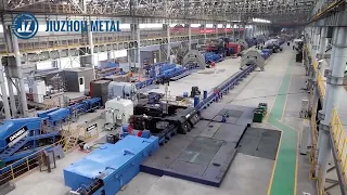
The machining of this part delves deeper into the manufacturing process of Atlas tube piles and provides insight into the meticulous steps that ensure their high quality and reliability. Atlas tube piles operate from a sprawling 500,000-foot facility located in Chicago. There are three production lines in operation at this Illinois facility. These production lines are capable of rolling an impressive 1,000 tonnes of tube piles in a single shift, all of which are of top quality. Quality guarantee from the beginning. The manufacturing process begins with hot rolling. steel coils from the beginning, quality control is a priority. Atlas technicians subject incoming steel coils to extensive testing to evaluate their tensile and yield strength properties, ensuring the flexibility and quality control essential to producing reliable tube piles.
The steel coils are then cut to the appropriate size. Depending on the diameter of the tube piles to be manufactured in a specific shift to form the tube piles, the cut coils are loaded onto the tube forming line as the steel is uncoiled and flattened, attached to the end of another coil through a butt weld. The weld is then cut and discarded, ensuring that only the highest quality materials enter the production process. The heat number of the steel used is etched on an identification stamp on the inside of the pipe, facilitating traceability to the steel source at the date of manufacture, efficiency and continuity.
To maintain maximum efficiency and continuity, an accumulator stores up to four coils, this configuration ensures that later stages of the process do not encounterdelays in material. The continuous coil of end-welded steel enters the spiral accumulator, allowing continuous change of coils without stopping production, shaping pipe stacks. The forming process employs five forming rolls that progressively shape the welded steel strip into a curved shape. The shiny, polished appearance of the rollers is a testament to their efficiency. These rollers can be quickly changed to accommodate piles of different diameters or gauges of steel. Rolling presses can be changed gradually.
Bring the ends of the strip together ensuring uniform alignment and clean, high-quality welds ERW Electrical Resistance Welding Atlas Straight Seam Pipe Piles are welded using ERW Electrical Resistance Welding This process involves passing electrical current through the edges of the strip. Pulls the coil using copper contacts Shims The resulting resistance generates heat with temperatures reaching up to 2700°F Despite these high temperatures The process maintains impressive speeds of up to 120 feet per minute The result is a continuous longitudinal weld characterized by finishing touches Precision and Quality Controls The excess weld seam is trimmed using a scarf cutter resulting in a smooth, nearly invisible seal, then the pipe is ironed to achieve the correct size and diameter for installation.
Ultrasonic testing follows the ERW welding process to verify weld integrity and detect any internal defects. Defective sections are automatically removed to ensure the highest quality standards, final steps and verification After confirming the integrity of the weld, the pipe is gradually cooled using water and coolant to prevent cracking or splitting. Turkish heads refine the pile to its final size and surface finish before cutting. The heat number is marked on the outside of the stack which matches the identification stamp engraved at the beginning of the process, this heat number ensures traceability and quality verification, destructive testing and certification.
Atlas pipe stacks undergo two destructive tests: the Code test and the flatness test, the former evaluating the integrity of the weld by applying hydraulic pressure until failure or a predetermined expansion occurs. Flatness testing involves flattening a specimen with the weld oriented vertically and horizontally to verify both the integrity of the weld and the ductility of the steel. Each Atlas pipe stack receives a barcode and an original Mill MTR test report backed by coil certificates from the steel supplier. Atlas Pipe Shipping and Reliability. Piles with lengths up to 125 feet are shipped directly to stocking partners and project sites throughout North America and beyond.
These pipe piles offer unmatched support for deep foundation projects. Backed by a commitment to quality efficiency and traceability, the EMC group spearheaded a revolutionary transformation in the field. of process automation that marks an important milestone in the evolution of industrial manufacturing recognized as a highly international industrial automation solutions platform. The EMC Group established a paradigm shift that would redefine efficiency, precision and quality within the manufacturing sector at the heart of this transformation. LM sees commitment to Leveraging cutting-edge automation technologies The group's innovative initiative aimed to automate a staggering 80% of machining processes and 70% of assembly processes through advanced automation lines.
This bold approach not only simplified production but also significantly improved the speed and precision of manufacturing operations, one of the notable features of the EMC revolution was its emphasis on visibility and transparency throughout the production cycle. The group integrated an ingenious process visualization system that gave stakeholders an unparalleled view of every step of the manufacturing process by making each stage of the production process visible from raw materials. to the final product The EMC group established a real-time monitoring and oversight environment that led to superior quality control and reduced inefficiencies. The benefits of this process automation. The revolution was multiple.
The greater integration of automation into machining and assembly processes led to faster production rates and greater minimization of precision. human error and consistent performance Superior results by providing operators with real-time data the system not only enabled faster decision making but also facilitated continuous improvement through the identification of bottlenecks and optimization opportunities cannot be achieved Underestimate the international reach of EMC's influence. The group's industry automation solutions platform transcended geographic boundaries by fostering collaboration and knowledge sharing between manufacturing companies around the world. This global perspective allowed various industries to adapt and implement automation solutions tailored to their specific needs, propelling the manufacturing sector into a new era of competitiveness and innovation.
CBA Industrial Automation in Germany is at the forefront of mechatronic manufacturing with its state-of-the-art production facility. A remarkable engineering feat is carried out within this facility, the production and testing of high-precision magnetic bearing motors, motor elements for synchronous motors, and intricate large-scale magnetic bearing elements. The process serves as the foundation of kba's long-standing Turbo solutions, which have earned a strong reputation in various markets, including high vacuum irration gas compression and power generation. The heart of kba manufacturing. Excellence lies in its ultra-modern production facilities. Here, a symphony of advanced technology and skilled labor. and Precision Engineering team up to create magnetic bearing motors that push the limits of performance and reliability.
These engines feature not only impressive power generation capabilities, but also exceptionally low levels of friction and wear. Thanks to the incorporation of magnetic bearings, this innovation results in reduced maintenance. need a longer life and higher overall efficiency the facility's focus on producing motor elements for synchronous motors is equally noteworthy Synchronous motors are critical in various industrial applications where precise timing and control are essential when mastering the production of these critical engine elements technological. Magnetic bearings are recognized for their ability to levitate rotating components without mechanical contact, leading to smoother operation, reduced vibration and minimized energy loss.
These elements play an indispensable role in Turbo solutions that operate in demanding environments, such as found in gas compression and high vacuum systems. Injection molding is a manufacturing process widely used to produce plastic parts in large quantities. The heart of an injection molding machine. It is its screw that plays a fundamental role in melting, mixing and injecting the plastic material into the mold cavity to create a high quality screw for the injection molding process. Layin CNC computer numerical control is used for precise and efficient machining of the screw used in an injection molding machine. It is designed with a helical flight channel that gradually compresses and melts the plastic granules as they move along the length of the screws.
This molten plastic is then injected into the mold to form the desired part. Screw design and precision have a great impact on quality efficiency and repeatability. of the injection molding process this is where CNC slats come into play. CNC lathes are advanced machining tools controlled by computer programs that enable complex and precise machining processes when processing injection molding machine screws. CNC strips ensure that screw profile dimensions and surface finish are designed to exact specifications this is how the process typically unfolds material selection common materials include steels, stainless steel and specialized alloys design translation design of the screws often in CAD format is translated into a CNC program this program guides the movements of the CNC LA to shape the screw accurately Precision machining The cutting tools of CNC lathes are used to gradually shape the helical channels of the screws, as well as their core and outer diameter in accordance with the design specifications.
The CNC system ensures that each cut is precise and consistent. Heat and surface treatment after the initial machining that the screw may undergo. Heat treatments can also be applied to improve its durability and resistance. Surface treatments such as nitriding can also be applied to improve wear resistance and reduce friction during operation. Quality control throughout the machining process. Quality checks are performed to verify that the dimensions and characteristics of the screws match the design requirements. This step ensures that the final product will perform as expected during injection molding assembly, depending on the design of the injection molding machine, the screw may be assembled with other components such as the cylinder and nozzle before installing it on the machine , the use of CNC lathes in manufacturing.
Screws for injection molding machines offer several advantages. CNC technology allows for high precision and repeatability, ensuring each screw meets the exact specifications required for efficient and consistent plastic injection. Additionally, CNC lathes can handle complex geometries and material properties, allowing manufacturers to tailor screws to the specific needs of different injection molding applications. The Boer extruder is state-of-the-art equipment designed to transform raw materials into a wide range of products through a complex process. Extruder operation is characterized by several key sequences, each of which contributes to its overall efficiency and functionality. The initial step involves assembling the screws. A crucial component of the extruder.
These screws are precision engineered to enable the desired mixing, cutting and cooking processes. Once assembled, the extruder is ready for the next sequence during startup. The extruder undergoes a systematic preheating process. Integrated heaters within the GR machine usually raise the temperature to the optimal range for processing simultaneously, the control system is initialized ensuring that all parameters are within the set safety limits as the extruder ramps up for production, raw materials Raw materials are introduced into the system, the synchronized rotation of the screws efficiently transport and mix the materials while subjecting them to controlled levels of heat and pressure.
This combination facilitates chemical reactions, cooking and the transformation of raw ingredients into the desired product. In case of an unforeseen circumstance, the extruder is equipped with an emergency stop mechanism. This safety feature stops all operations instantly, preventing potential accidents or damage to equipment. Once the situation is resolved, the extruder can be restarted gradually following proper procedures to facilitate maintenance and prevent material degradation within the extruder. An automatic screw extraction process is used. This procedure removes any residual Material from the system which prevents cross contamination and ensures the machine is ready for the next production cycle. For a change in product type or recipe adjustment, the extruder offers a seamless transition by reprogramming the control system and adjusting specific parameters.
Operators can adapt the process. To meet new requirements, this flexibility is essential for product diversification and quality optimization. Finally, when it is time to conclude operations, the shutdown sequence is initiated, the extruder gradually reduces its temperature and stops completely while maintaining adequate purge to prevent residual material from clogging the system. This careful shutdown process ensures the longevity of the extruders and efficient start-up for thenext production. The bus technology stands out for its exceptional mixing capabilities based on a distinctive operating principle involving simultaneous rotation of the screw shaft and axial oscillation. This innovative bus-initiated approach is the original.
The manufacturer allows those in need to achieve both axial and radial mixing at controlled cutting speeds. The latest versions of this technology, namely the Quantech G3 and MX, exemplify high-performance machine concepts built on the tried and true operating principle of the reciprocating screw, particularly the integration of four-light technology. has produced substantial improvements in performance, particularly for heat- and shear-sensitive compounds. Key features and benefits of Neer bus technology. It covers an incredibly compact processing length ensuring efficient operations. This is accompanied by uniform cutting effects without temperature peaks that contribute to improving product quality. Additionally, the technology facilitates precise temperature regulation and maintains significantly lower product temperatures, critical to improving process control and final product characteristics.
Another benefit is the achievement of a narrow residence time distribution, which improves the consistency and quality of the materials produced. An extrusion machine plays a vital role in the automated production of a wide range of confectionery products, including cereal bars, protein bars, chocolate bars and more, this ingenious machine efficiently shapes semi-finished materials into these delicacies. . It accepts various confectionery masses with different densities, consistencies and compositions, such as sandy dough for shoes and protein-based mixtures. By extruding the confectionery dough through specialized nozzles, the machine forms an uninterrupted line of products later segmented into bars of specific lengths according to the desired result.
These bars can be baked, glazed or packaged. The extrusion process also allows for the incorporation of fillers, facilitated by dedicated equipment. Boer snack fix feeding and filling station is a compact and efficient system designed for the optimized production of cereal and fruit bars. This innovative solution simplifies the entire bar-making process, making it an ideal option for companies looking to produce these popular snacks with ease and precision. The snack fix system consists of two main components that work harmoniously to create a perfect production line. The process begins with the preparation of the binder, which is achieved through rapid, automated mixing and dosing.
The compensating rollers ensure a consistent shape before the precise cutting step is performed, particularly the snack. The Fix system offers flexibility due to its modular design. The operation of the Fix snack is simple. The water-powder mixture is heated up to 80 C, followed by loading the mixture serially into the hopper. The preheated container then receives the prepared binder after the process is complete. started, the system is responsible for forming and cutting the bars, the products are briefly stored before undergoing optimal cutting and subsequent packaging using the flow wrapper. The Samsung sl25 asy CNC lathe is a versatile machining tool designed for precision turning and milling operations, in this case we will explore how it works when
working
with a 22 6.061 bar.The machining process begins with loading a 2 1/2 diameter 661 aluminum bar onto the lathes. The chuck firmly holds the material in place, allowing precise rotational movement when turning the Acme thread. Once the material is loaded and secured, the lathe spindle rotates the bar while the cutting tool positioned along the z-axis engages the material to cut the desired piece of Acme thread, the CNC control system controls with precision the depth and pitch of the thread, ensuring precision in consistent results offc Center ya AIS Milling lathe sl25 asy ay AIS features that can be offset from the center line of the material, allowing the machine to perform offset milling operations, in this case the y-AIS is used to create complex features in the workpiece, such as cavities or slots away from the centerline for finish drilling after threading and offset milling operations, the machine can perform finish drilling, the boring tool advances along the z-axis, precisely enlarging the diameter of existing holes to the desired one. specifications, this process ensures tight tolerances and a smooth, precise board cam groove with live tooling.
One of the most notable features of the SL25 ASY is its live tooling capability, meaning the machine's turret holds tools that can rotate and perform operations while the workpiece is stationary to create a cam groove, a tool active is activated, the turret indexes the appropriate tool into position and the CNC control system precisely directs the movement of the tools along the x and z axes by cutting the cam groove in the workpiece or stepping back to chamfer once. As the cam slot is created, the active tool can be programmed to retrace its path and add a chamfer to the edges of the slot.
This chamfer improves the functionality and aesthetics of the cam. The groove and CNC control system ensure that the chamfer is applied accurately. Ok, cut and transfer after completing the whole process. required machining operations the lathe is ready to perform the cutting operation the active tool can be replaced with a cutting tool designed to part off the tool feeds along the z axis cutting the material and separating the finished workpiece from the rest of bar The newly machined part is now a separate material transfer component. Once the part is cut, it needs to be moved from the main spindle area for unloading or further processing.
The lathe may have automation options, such as a robotic arm to transfer the finished part to a designated location. collection area in this part we will learn about the Nordstream gas pipeline installation project the Nordstream project is installing 248 export gas pipelines from Viborg in Russia to Graal in Germany through the Gulf of Finland and the Baltic Sea the two 1,224 km offshore gas pipelines are The most direct connection between the vast gas reserves in Russia and the combined European Union energy markets. The twin pipelines have the capacity to transport a combined total of 55 billion met3 of gas per year to businesses and households in the EU for at least 50 years as the project strengthens the EU energy market and reinforces security of supply.
The project has been designated of European interest by the European Parliament and the Council. Each of the two Nordstream gas pipelines is built in three sections. Once completed, the sections have been welded together. To form the 1,224 km pipelines, this connection process was carried out on the seabed in an underwater welding habitat. Welding operations were controlled remotely from the sleek Arctic diving support vessel and divers helped monitor Subia's construction work. This is the phf pipeline management framework. The phfs move the ends of the pipe to the mooring position. They can lift up to 150 tons. Lifting bags are installed in the segments and filled with air.
Once filled, the bags can lift up to 20 tons, helping PHF handle extremely heavy pipe segments. The phfs not only lift the pipe sections, but also move them sideways to align them for welding. This is the connection equipment, the habitat of welding. Supply by stoil PRS is a dry area where divers work without diving equipment to set up the automatic welding machine. It is completely controlled from the diving support vessel the state-owned company PGN perahan gas ngagara supplies gas to more than 80 million customers in Indonesia one of its main offshore gas pipelines transporting gas to Jakarta showed signs of leaking during an inspection in 2013 and was temporarily repaired with a dcn clamp International diving and Marine Contractors and its Indonesian partner SGI knew PGM had contracted to seal the tear in the four-year-old pipe.
PGN decided to carry out a permanent repair of the 32 in 81 CM pipeline at a depth of 27 M 89 ft while the pipeline remains fully pressurized, 15 divers will be specially trained for the PGN project here in dcn at Bergen up Zoo, of the which 10 pre-qualified divers will eventually be deployed. Of this team, nine divers will spend approximately 1 month in saturation in order to carry out the repair according to the welding method dcn proposes that this is a challenging project because the repair had to be completed without closing the pipeline. The contractors developed a methodology to stop the leak from the temporary pipe repair clamp in place based on a comprehensive analysis of the bending moments at the intersection and a permanent repair was carried out using welded structural sleeve ensuring long-term integrity. term of the rest of the useful life of the pipe to be able to comply with this project.
DCN proposed to carry out the welding work dry underwater. conditions by using what is known as a habitat a habitat is a sealed work space that offers divers a safe and secure
working
environment while they are on the seabed during the summer here in Bergen op Zoo DCA carried out a series of drills and tests DC Infinitely simulated all the elementary welding tasks necessary to ensure the long-term success of the repair at its own location (we will find it in Indonesia). In fact, the tests were carried out by the same divers who would eventually be required to carry out the repair. working at a depth of 27 m in the Java Seat under considerable pressure after an extensive testing program all risks were identified, minimized and managed containers with equipment were sent to Singapore, including the complete diving system by saturation and habitat with suction anchors.The Norman Baltic dive vessel, dp2, equipped with a 100 metric ton lunar crane and a helicopter platform, was chartered for the project. Piles 5.6 m long were installed on the seabed composed of silt and clay. The first pile was used as a test to determine the required suction force and to calculate the theoretical load capacity, the habitat subsequently had to be placed on the four remaining piles, after hermetic sealing and purging of the habitat to lower the level of the water, the first gas containment barrier was placed, a type of safety clamp was placed. Mounted on the pipe, followed by the lower and upper sleeves, divers were able to begin the demanding welding process while gas continued to be pumped through the pipe over a period of 10 days.
The welding was carried out in an interrupted manner while the welded layers underwent a continuous process. ultrasonic tests to finally place an anti-corrosion coating on the repaired section of the pipeline Four decades ago the Brent field platform was a symbol of industrial power and energy prowess these platforms located in the North Sea played a fundamental role in generating energy for the homes and But as time passed, the inevitable question arose: how would these enormous structures be dismantled? The Brent field platforms, after years of dedicated service, were scheduled for decommissioning. The challenge was immense, as these platforms were not designed to be lifted in the manner required for removal. 2017 Shell surprised the world by lifting the Brent Delta platform intact and transporting it for recycling.
This set the stage for Brent Bravo's turn. The task was not only to repeat the process but to improve it. The objective was clear to lift the top 25,000 tonnes of Brent. Bravo from its base in the North Sea and transport it safely for recycling, this was no easy task, especially considering the design of the platform and the unpredictable nature of the seashell approach approach. The approach was innovative, rather than attempting dismantling on site the decision was to remove the entire upper deck or upper sides as a single unit, this involved isolating the reservoir to ensure no hydrocarbon could escape, evacuating personnel and then preparing the uprising.
The process was simplified with lessons from the Delta lift, leading to a 70% reduction in preparation work for Bravo, a significant challenge was how to free the Bravo from its 150 M high base without using steel reinforcement. that was used for Delta the solution Transparent keys were inserted into the concrete walls of the legs of theplatform providing strength and stability once in place a diamond wire cutter cut through the concrete wall ensuring the platform was ready to go up. The world watched When the pioneering Spirit, the world's largest construction vessel, approached the Brent field, this ship with its unique double-hull design was an integral part of Shell's unique lift concept.
The vessel's advanced technology allowed it to connect its lifting arms to Bravo with millimeter precision, ensuring no contact with the platform. legs and then, in an impressive moment, 25,000 tons were lifted in just 9 seconds. The success of the operation was a testament to the meticulous planning coordination and engineering prowess of the team involved, but the journey was not over. The pioneer Spirit transported Bravo to the Harley Pool. where she awaited another engineering marvel, the barge Iron Lady, the upper part was transferred to this barge which was then towed to the appropriate facilities for recycling. Shell's commitment to doing things right was evident, its partnership with Abel promising a 98% recycling rate at the Brent field. which had been part of oil and gas history for 40 years, is now setting a new standard in environmental responsibility, the Prelude flng, after traveling almost 6,000 kilometers, has arrived in Australia.
Its mission to produce liquefied natural gas for a quarter of a century, but before that, the mammoth task. mooring facility the world's largest floating facility awaits located 200 km off northwest Australia a dedicated rigging team begins the process their goal for the day is to secure the eighth leg of the move this is not just another day's work the Prelude when fully Loaded it weighs a staggering 660,000 tonnes, six times heavier than the world's largest aircraft carriers given its location in a region famous for its extreme climate. The reliability of motion systems is paramount. It is designed to resist cyclones.
Keeps the installation securely anchored. The heart of the movement system is the turret inside Prelude, which allows it to rotate. Below lies one of the largest chains in the world with almost 25,000 links anchored deep to the ocean floor. The team is now ready to connect the eighth chain ensuring the safety of Prelude against storms. The process is complex. The rigging team descends into the depths of the turret while the tugs maintain the preludes. position the Deep Orient crew recovers the line of motion and a colossal winch on Prelude is ready as the chain is dragged Engineers monitor every move the culmination of years of planning is in action the rise of the chain is a sight to behold a specific link indicates the correct direction length of chain that ensures the facilities are anchored to the seabed once the eighth line of movement is connected Prelude reaches its storm-safe state this is just one of the 16 lines of movement that will maintain a Prelude anchored for the next 25 years, a historic moment in fact, AA Hansin Spar is a marvel of modern engineering that represents a major milestone in offshore natural gas extraction, located 186 miles offshore in the Norwegian Sea, is operated by Equinor and stands as the first Spar platform on the Norwegian continental shelf NCS, the platform is named after Austa Hanstein, a renowned Norwegian painter and writer and early feminist Design features The Austa Hanstein platform is a Spar frame type that allows storage of condensate in waters below sea level.
This condensate can then be discharged into a tanker truck. The produced gas is exported to the coast using steel catenary risers. Marking the first time scrs have been used in the Norwegian Sea, the deck design is a collaborative effort with The Spar hle designed by Technip and the topsides by CB and myself. Both components were manufactured by Hyundai Heavy Industries in South Korea before being transported to Norway. for installation The Spar Hull with a height of 198 M 177 M submerged and a diameter of 50 m is the largest of its type in terms of diameter and displacement the platform exports natural gas via the polar gas pipeline to the Nyhamna processing plant on the Norwegian coast Since the entire project cost approximately 37.5 billion Norwegian crowns, transportation and installation, the construction process of the AA hin Spar was unique: it was built sideways in the dry dock on barges, floated and It was then transported on the heavy ship Vanguard at the dock to a nearby location. in western Norway on the F.
The Spar was capsized and the upper sides installed using the flotation technique. The platform was then towed vertically to the AA Hansin gas field, 300 km from Bodo, on the northwest coast of Norway, and located further north of the Arctic Circle using polyester moorings anchored to the seabed 1200 MERS below the production began on December 17, 2018 The AA Hanstein gas field originally known as lava gas field and renamed after AA Hansin the field was discovered in 1997 approximately 300 km off the coast of Norway as the platform launched march gas from the surrounding hacklang and sniffer lava fields that were exported to it.
There are plans for the future. It has already been discovered that the fields are linked to Austa Hansin's platform via scrs. The platform design also accommodates future expansion of additional elevators and overhead facilities. North of the Arctic Circle, the field faces perpetual darkness and sub-zero temperatures during the winter. The Suez Canal, one of humanity's most monumental achievements, serves as a vital maritime passage for more than 177,000 ships a year; However, there was a significant limitation: a 35 km stretch only allowed one-way traffic. causing ships to wait up to 11 hours for ships coming in the opposite direction this inefficiency led to an improvement in the 21st century a new parallel canal to facilitate two-way traffic originally experts estimated a completion time of three years however the president Egyptian ambitiously intended to inaugurate the new In one year, the canal launched an unprecedented operation with minimal preparation.
The project was handed over to a consortium that set a daunting goal. Complete the channel in just 10 months. Teams from around the world, including Europe, Asia and South America, converged on the site. The result was a 35km Canal, 24m deep and 400m wide, dug directly through the desert, the scale of the project was staggering; In total, 200 million cubic meters of sand were excavated, equivalent to relocating 80 great pyramids of Giza. At its peak, production reached 65,000 cubic meters per day. The nerve center located in Iselia oversaw logistics and equipment with 28 units, the largest number of dredges ever used on a single project with almost 1,800 employees on site and 23 dredges operating simultaneously.
Coordination was essential. The team worked tirelessly to ensure any issues were quickly addressed with operations. running 247 Moror Steel Industry is a leading player in the steel industry and is well known for its high quality steel products. In this part of the video we will explore the free forging process in your factory, specifically forging a gear blank from a square bill. The use of a large hydraulic press machine. Free forging is a process in which metal is given the desired shape without the use of dyes or tools. This process is widely used in the steel industry for the production of a variety of components, including gears.
Free forging involves heating the metal to a temperature where it becomes malleable and then applying pressure to shape it into the desired shape in the mill. The first step in the process of forging a gear blank from a square billet is to heat the steel billet to a temperature of about 1, 1200° C. This temperature is necessary to make the metal malleable enough for the forging process. The bill is then placed into the forging machine, which is a large hydraulic press. The next step in the process is to forge the steel billet. In a round shape, this is achieved by applying pressure to the bill using the hydraulic press.
The hydraulic press is a powerful machine that can apply a large amount of force, making it ideal for forging metal. The round shape is important because it provides a base shape for the gear blank that will be formed once the billet has been forged into a round shape, the next step is to drill holes in the metal to form the gear blank, the hydraulic press is Used to apply pressure to the metal, causing the metal to flow into the holes forming a drilled circular shape, the size and number of holes drilled depend on the desired size and shape of the gear blank.
Ingersol Cutting Tools is a leading manufacturer of cutting tools for various industries, including gear machining. Gear machining is a process of cutting and shaping gears to precise specifications for use in various applications. Ingersol cutting tools offer a wide range of gear machining tools, including solid carbide end mills, indexable carbide inserts and high speed steel milling cutters. These tools are designed to provide high precision, efficiency and productivity in gear machining. Process One of the key benefits of using Ingera cutting tools in gear machining is the company's focus on technological innovation and technology. The company invests heavily in research and development to develop cutting-edge tools and solutions for gear machining, such as its patented Power Feed Plus Hob system. which improves cutting speed and precision while reducing tool wear.
Mitsubishi Nagasaki Machinery's fully automatic ring production line is a state-of-the-art system that uses advanced technology to produce high-quality rings with precision and efficiency. The production process begins with loading the raw materials. material on the conveyor belt which is then fed to the rough terrain forming machine. The rough terrain forming machine shapes the material into a ring and then transfers it to the rolling mill. The rolling mill applies pressure and heat to the ring, gradually forming it into the desired shape. Shape and size, the finished ring is then transferred to the material handling system for discharge throughout the production process.
Various sensors and cameras monitor temperature, pressure and other key parameters to ensure the quality of the finished product. The entire process is completely automated from loading the raw materials. material to discharge the finished product, minimizing the need for human intervention and increasing efficiency BM gears is a leading manufacturer of gears and transmission components located in Italy. The company has a wide range of gear cutting machines including cling lurg c29 machine which is used for dry cutting bevel gears in this part we will show the process of dry cutting of bevel gears on Kingberg C29 machine and how BM Gears Use this machine to produce high quality bevel gears with module M5.5 and 22 teeth.
Kingberg C29 machine is a highly advanced machine. Bevel gear cutting machine that uses a dry cutting process. Dry cutting is a process that involves cutting gears without the use of coolant or lubricant. This process is environmentally friendly as it eliminates the use of cutting fluids that can be harmful to the environment. It is also cost effective as it reduces the need for expensive cutting fluids and associated disposal costs. The dry cutting process on the Cling Leberg C29 machine begins with the preparation of the gear blank. The gear blank is a piece of metal that is cut to the desired shape. gear size and shape, then mounted on the machine and placed in the cutting area.
Then the cutting tool, which is a bevel gear cutter, is placed in the machine and adjusted to the correct angle and depth once the cutting tool is in position. The cutting tool rotates at high speed and cuts the gear blank, removing the metal and creating the gear teeth. The cutting process is controlled by the machine's computer system, which ensures that the gear is cut to the precise specifications required. The computer system also monitors the cutting process and makes any necessary adjustments to ensure that the cutting tool cuts the gear correctly. BM Gears uses the Kingberg C29 machine to cut bevel gears with m5.5 module and 22 teeth.
This is a common gear configuration used in a variety of applications including automotive transmissions and industrial machinery. M Gear's use of the kingberg c29 machine ensures that the gears they produce are of thehighest quality and precision. In addition to its dry cutting capabilities, the kingberg c29 machine also has other advanced features that make it a highly effective gear cutting machine. These features include a high-speed spindle, precision cutting tool, and sophisticated computer control system. The combination of these features allows the machine to produce high precision gears with excellent surface finish and low noise levels. Bevel gears can be manufactured. cut on a shaping machine using a rotary table and a special cutter called a bevel gear cutter.
The process involves mounting the workpiece on the rotary table and aligning it with the cutter. The cutter is then inserted into the workpiece at the desired angle and depth for cutting. The rotary table is then rotated to the next position and the process is repeated until all the teeth are cut. Proper alignment and configuration are critical to ensuring the accuracy of the gear teeth. The cutting speed, feed rate and depth of cut must also be carefully selected to produce a high quality gear. Lieber, a world leader in advanced engineering, has recently introduced a next-generation gear hobbing and profile hobbing machine, the LC 4000.
This machine is designed to work with workpieces up to 4,000 mm in diameter and is capable of producing High quality gears and profiles with exceptional precision and efficiency. One of the key features of the LC 4000 is its high rigidity, which allows it to maintain stable cutting conditions even when working with large workpieces. This is achieved through a robust machine built structure. To withstand high cutting forces and vibrations, the machine is also equipped with a powerful drive system that ensures smooth and precise motion control. In addition to its rigidity, the LC 4000 is also designed for maximum versatility. It is equipped with a range of hobbing and milling tools that can be easily interchanged to produce different types of gears and profiles, this makes the machine ideal for a wide range of applications, from small scale production runs to mass production. big scale.
Another important feature of the LC 4000 is its advanced control system. The machine is equipped with a sophisticated CNC control system that provides precision. Control of all machine functions The control system is easy to use and intuitive, allowing operators to easily program and adjust machine settings as needed to ensure the highest levels of quality and precision. The LC 4000 is also equipped with a range of advanced sensors and monitoring systems. The systems are designed to detect and correct any deviations from the program settings, ensuring that the final product meets the required specifications. The LC 4000 is also designed with efficiency in mind.
It is equipped with a range of automation features that help reduce setup and changeover times. This includes a quick tool change system that allows operators to quickly and easily change hobbing and milling tools, as well as an automatic workpiece loading system that eliminates the need for manual handling. Heat treatment is a critical process in gear manufacturing. The heat treatment process. It involves heating the gear to a specific temperature and holding it there for a set period of time before cooling it in a controlled manner. This process alters the structure of the metal and improves its mechanical properties, making it stronger and more durable.
The okubo gear installation is equipped with several different types of heat treatment, including carburizing, quenching and tempering. Carburizing involves adding carbon to the surface of the gear to increase its hardness, while quenching rapidly cools the gear to increase its strength. Tempering involves reheating the gear to a specific temperature to reduce its brittleness and improve its hardness. Forged flanges are essential components in various industrial applications that serve to safely connect pipes, valves and other equipment. The chosen material must have the necessary mechanical properties and corrosion resistance. A cylindrical metal piece known as Billet is prepared by cutting, heating and shaping it to the required size and shape, the billet is heated to a suitable temperature and placed in a forging machine.
It is then subjected to tremendous pressure, causing it to deform and take the shape of a flange. The forging process ensures grain alignment and improves the mechanical properties of the fl. forged Excess material is trimmed and the center hole is drilled to match the diameter of the pipe. This step ensures that the flange fits accurately. The forged flange is heat treated to improve its metallurgical properties, making it more resistant to stress corrosion and wear. Additional machining to achieve required dimensions and surface finish. This step ensures that it will fit perfectly with other components. The final product is subject to rigorous quality control measures including non-destruction testing and dimensional inspections to ensure it meets industry standards and customer specifications.
It is usually coated or painted to protect it from corrosion The 60K Press The world's largest closed die forging machine operates with
incredible
precision and power Here is a brief description of how it works The heart of the 60K press is its immense forging force that is generated by a hydraulic system a huge hydraulic pressurization system applies a tremendous load to the upper die exerting a force of 540 mega Newtons equivalent to 60,000 short tons. This force is essential for shaping and compressing the metal to the desired shape. Closed D forging involves two dyes, the upper Dy. and the lower Dy, these dyes are specially designed to fit precisely and create the desired shape.The metal piece is usually placed a superheated ingot between the dyes. The metal piece is heated to a precise temperature to ensure it is malleable and ready to forge at this temperature. varies depending on the type of metal being used with the heated workpiece placed between the dyes, the press applies the enormous forging force, the upper Dy is driven downwards while the lower Dy remains stationary, this compresses and shapes the metal within the confined space of the dies. What sets the 60k Press apart is its high level of precision and automation. It incorporates advanced digital technology and a network of more than 3,000 sensors to monitor and control the entire process.
This automation ensures that the forging process is not only powerful but also incredibly precise, narrowing down the possibilities. of defects in the final product The heavy forging industry is a cornerstone of manufacturing and provides essential components for various sectors, including aerospace, automotive energy and defense. It relies heavily on sophisticated machinery and equipment to transform huge metal ingots into precision engineered parts. The role of heavy machinery in this industry is fundamental both in terms of production efficiency and the ability to meet strict quality requirements. In this article we will delve into the world of heavy forging machinery and the critical numbers that underline its importance.
Hydraulic Forging Presses Hydraulic forging presses are workhorses of heavy industry. Forging industry capable of exerting immense pressure to shape metal. These machines come in various sizes with tonnage ratings that represent their power. For example, a 10,000-ton hydraulic press can apply 20 million PBS of force to manipulate metal. These presses are essential for producing large components such as shafts, gears and turbine discs, mechanical forging presses. Mechanical forging presses, although less common than their hydraulic counterparts, still play an important role in heavy forging operations, these machines use a mechanical drive system, typically a crankshaft and an eccentric drive to apply a force to the workpiece. work of 4000 tons.
The mechanical press, for example, can generate 8 million pounds of pressure for metal shaping tasks. These presses are known for their speed and precision, making them suitable for specific applications. the workpiece the weight of the hammer expressed in pounds determines the force applied to the metal, for example a 10,000 pound drop The hammer exerts a considerable impact on the material allowing efficient deformation and shaping of larger parts steam hammers hammers Steam hammers have historical importance in forging and were an important innovation during the Industrial Revolution, these hammers use steam power to strike the workpiece. Steam hammers come in various sizes and their power is often measured in feet PBS.
A medium-sized steam hammer can deliver 50,000 to 100,000 ft-PBS of power, allowing precision and versatility in metal forming modern CNC controls the integration of computer numerical control CNC systems into heavy forging machinery has revolutionized the industry CNC controls allow precise programming of forging processes leading to consistency and repeatability Accuracy is often measured in micrometers, muum or thousands of Modern one-inch CNC forging machines can achieve such tight tolerances as zero, 0.5 in 0.127 mm, ensuring that forgings meet strict quality standards. Manipulator robots. Manipulator robots are used to manipulate and position heavy workpieces during forging. tons to 50 tons or more, allowing them to maneuver the huge ingots used in heavy forging.
The precise control of these robots ensures worker safety and positioning accuracy during forging operations. Induction heating systems. Induction heating is a critical aspect of the heavy forging process. While preparing the metal for deformation, the power output of induction heating systems is measured in kilowatts KW. A high power induction heating system can deliver up to 1000 Kow or more. This high intensity heat source allows rapid and controlled heating of the workpiece to the required forging temperature often in a matter of seconds Die Design Software Die design is an essential aspect of heavy forging as the Shape and quality of dies directly impact the final product Specialized die design software uses 3D modeling and finite element analysis to optimize dies, helping engineers create dies with intricate shapes and contours, ensuring that dies forged parts meet the desired specifications.
Modern die design software can reduce lead times and material waste, while improving component life and quality. Forging material handling equipment. Heavy forging involves the manipulation of solid metal. Ingots that can weigh several tons, overhead cranes and mobile gantry systems are critical pieces of equipment used to transport these heavy materials. These systems often have lifting capacities ranging from 5 tons to 50 tons, allowing for the efficient movement of ingots and forged components within the facility material. Testing equipment that ensures the quality and integrity of forged components is of utmost importance. Materials testing equipment, such as ultrasonic testing machines and magnetic particle inspection systems, are used to detect defects or irregularities in forgings.
These machines provide precise measurements, often in millimeters or micrometers, to ensure that components meet required quality standards. Heat Treatment Furnaces Heat treatment is a crucial step in the heavy forging process to improve material properties. Large heat treatment furnaces are used to subject forged components to specific temperatures. These furnaces can reach temperatures in excess of 2000°C (3632°F) and are equipped with advanced control systems to maintain precise temperature tolerances Environmental controls as in any heavy industry Environmental considerations are essential Heavy forging facilities incorporate control systems Advanced environmental to manage emissions and energy consumption these systems help reduce the environmental footprint of heavy forging operations while meeting regulatory requirements Automation and robotics Automation and heavy forging have gained ground driven by necessity of efficiency and precision.
Robotic systems are usedincreasingly for tasks such as loading and unloading materials, die handling and quality inspection. The number of industrial robots in heavy forging facilities is increasing, which contributes. To improve worker productivity and safety Safety Systems Safety is a primary concern in the heavy forging industry due to the high forces and temperatures involved. Safety systems, including emergency stop mechanisms, safety interlocks and personal protective equipment, are essential to ensure the well-being of workers and the protection of valuable equipment. Energy consumption and efficiency Heavy forging operations are highly energy intensive. Energy and energy consumption is often measured in megawatt hours MW to improve sustainability the industry is investing in energy efficient technologies such as recuperative heat exchangers and energy recovery systems that can significantly reduce energy consumption maintenance and reliability forged Heavy machinery requires robust maintenance programs to ensure optimal performance and longevity.
The industry often measures machine reliability using metrics such as time between failures mtbf and time between failures to repair m TTR to minimize downtime and maximize productivity. Forging is an ancient manufacturing technique that has undergone notable evolution over the centuries, this process involves shaping metal by applying heat and pressure, usually through the use of hammers or mechanical presses, the development of forging technology It has been a journey from primitive blacksmithing to the precision and automation of the modern era in this In this article we will explore this journey by highlighting the key milestones and innovations that have shaped the forging industry.
The ancient origins of forging can trace its roots to ancient civilizations. The first forges date back to 4500 BC. and they were rudimentary facilities where metals were heated and heated. hammered into shape initially blacksmiths relied on simple tools and their skills to manually shape metals. Early Innovations One of the most significant early innovations in forging technology was the discovery of various metal alloys. Bronze, an alloy of copper and tin, played a fundamental role in the advancement of forging during the Bronze Age, around 3000 BC, allowing the creation of more durable and sophisticated tools and weapons. The Iron Age, which began around 1200 BC, marked a crucial turning point in iron forging technology; due to its abundance and malleability, it quickly replaced bronze.
As the preferred metal, blacksmiths honed their skills to create complex objects, from weapons to agricultural tools. The role of water-powered hammers The arrival of water-powered hammers in the Roman Empire introduced a more efficient way of shaping metal. These hammers use kinetic energy. of falling water to deliver powerful blows significantly reducing the physical labor required the Middle Ages and the rise of craft guilds during the Middle Ages the art of forging continued to evolve and craft guilds began to emerge these guilds established standards for quality from forged products and apprentices trained in the techniques of the trade skilled blacksmiths produced intricate armor, swords and decorative items the Industrial Revolution The Industrial Revolution that began in the late 18th century had a profound impact on forging technology the invention of machines The mass production of forged items at this time saw the birth of large-scale forging operations and the development of the steam hammer by James Naith in 1837, which greatly improved efficiency and precision.
The impact of advances in measurement, particularly in the 19th century, led to greater understanding of the properties of different metals and alloys. The ability to control and manipulate the micrometric structure of metals through heat treatment processes revolutionized the Forging industry, for example, the Besser process for steel production patented by Henry Besser in 1856 made high-quality steel more available for forging. Applications World War I and 2 The forging industry played a critical role during the World Wars. The demand for precision forged components, such as aircraft, tank and artillery parts, drove innovation and improvements in forging technology; It was during this time that the use of hydraulic presses and drop hammers became widespread.
Modern Precision Forging The second half of the 20th century witnessed a transformation in forging technology driven by advances in materials science automation and computer DEA design and CAD C manufacturing. Precision Forging , a technique that produces nearly net-shaped component opponents with minimal waste, emerged as a game-changer. Numerical Control CNC Forging The integration of computer numerical control CNC systems into forging processes revolutionizes the industry CNC forging machines allow precise control of temperature, pressure and deformation, resulting in components with tight tolerances and improves the properties of the material. This shift towards automation and precision has been particularly important. In the automotive aerospace industries, materials have been improved and all the development of advanced materials such as titanium and superalloys has expanded the applications of forging technology.
These materials offer high corrosion resistance and other desirable properties. Forging has played a vital role in transforming these materials into critical materials. components for medical and energy applications aerospace simulation and modeling computer-aided engineering CAE and finite element analysis Fe have become essential tools for optimizing the forging process these simulations help engineers predict how a material will deform under various conditions, leading to more efficient and cost-effective designs Innovations in D Design The design of forging dyes that shape metal has evolved significantly Computer DEA Design Computer DEA manufacturing cams have enabled complex die designs that reduce the need of secondary machining operations Environmental considerations in the modern era Environmental concerns have led to the development of cleaner and more efficient forging processes Technologies such as electromagnetic forming and isothermal forging aim to reduce energy consumption and emissions while maintaining the same time product quality 3D printing and additive manufacturing The emergence of 3D printing and additive manufacturing technologies has begun to impact the forging industry while these technologies are Non-traditional forging methods offer new possibilities for creating intricate shapes and designs in metals that can complement traditional forging techniques.
Smart manufacturing. The concept of smart manufacturing that incorporates the Internet of Things. IoT data analytics and artificial intelligence are being applied to forging operations. This allows real operations to be carried out. -process time monitoring predictive maintenance and continuous improvement future directions as forging technology continues to evolve, there are several promising areas of development including the use of advanced materials such as carbon fiber composites, increased automation with robotic systems and greater sustainability through recycling and waste reduction. A 5000 ton forging machine is a massive hydraulic press used in the manufacturing industry to forge metal parts. This machine works on the principle of hydraulic force to apply pressure to the metal workpiece which is then compressed and shaped according to the desired shape and size of the forging.
The process begins by heating the metal workpiece to a temperature where it can be easily formed. Once the metal is hot, it is placed in the lower Dy of the forging machine and the upper Dy is lowered to apply pressure. The machine's hydraulic system provides the force necessary to move the upper die down with tremendous force that compresses the metal between the two dyes. The 5,000 ton forging machine has the capacity to apply up to 5,000 tons of pressure, which is huge. This force is enough to shape even the toughest metals such as. steel or titanium, the metal workpiece is slowly molded and compressed between the two dyes and hydraulic pressure is maintained until the desired shape and size is achieved.
The hydraulic system of the forging machine consists of a large piston driven by a powerful hydraulic pump. Hydraulic fluid is stored in a reservoir and pumped to the cylinder that moves the piston. The movement of the piston is transferred to the upper D which applies pressure to the metal workpiece. The 5000 ton forging machine also has a range of features that make it a versatile machine. tool for forging different shapes and sizes of metal parts, the machine can be programmed to perform different forging processes, such as stretching, shaking, punching, forging, bending, shifting, chopping and cutting, among others, these processes are essential to create complex shapes requiring precision and accuracy, the machine is also equipped with advanced controls that allow operators to monitor and adjust the forging process depending on the metal being forged, the controls also ensure that the machine operates safely, preventing accidents and reducing downtime.
End mills are cutting tools used in milling applications to remove material from a workpiece by rotating the tool along its axis, the aerospace industry has unique requirements for cutting tools and end mills to High speed processing of aluminum are a common choice due to their efficiency and precision. In this part we will discuss the features and benefits of end mills for high speed processing of aluminum. Processing speed in the aerospace industry The aerospace industry is one of the most important sectors of the global economy generating billions of dollars in revenue each year. The aircraft component manufacturer requires high-precision machining tools capable of processing a wide range of materials, including aluminum.
It is a popular choice for aerospace components due to its light weight, high strength and corrosion resistance to meet the demands of the aerospace industry. Milling cutters have been developed for high speed processing of aluminum. End mills are cutting tools used in milling applications to remove material from a workpiece. They have a rotating cutting surface with multiple teeth that can remove material from the workpiece as they rotate. Strawberries come in different sizes and shapes and each one is designed for a specific purpose. Aluminum high-speed processing milling cutters are designed to work with aluminum. Material that requires high speed machining to achieve the desired finish.
The aerospace industry demands precision and accuracy in every component used in aircraft, from the smallest parts to the largest structures. Milling cutters for high-speed processing of aluminum are essential for creating precise, high-quality parts. Especially in the aircraft industry, these end mills have a variety of features that make them ideal for working with aluminum, for example, they are designed with a high helix angle which helps reduce vibration and improve chip evacuation. One of the important challenges of machining aluminum is to prevent the material from melting during the machining process, this can cause damage to the tool and workpiece, resulting in a poor finish.
To overcome this problem, aluminum high-speed processing milling cutters are manufactured with specialized coatings that provide high-temperature resistance. These coatings can help. To reduce the heat generated during machining, improving tool life and surface finish, another challenge in machining aluminum is the material's tendency to stick. The cutting edge of the tool, known as end mills for high speed processing of aluminum, is designed with a coating that helps reduce wear, the coatings create a barrier between the aluminum and the cutting edge of the tool, preventing the material from sticking and reducing the risk of damage to the tool or workpiece, in addition to the coatings, the end mills for high-speed processing of aluminum are also made from high-quality materials that can withstand the rigors of high-speed machining. speed.
These materials are oftenMade of solid carbide, a hard, durable material that can withstand high temperatures and high speed machining. Solid carbide shank end mills are also wear-resistant, which can increase tool life and reduce the need for frequent replacements.
If you have any copyright issue, please Contact