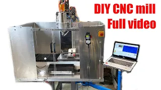
Building a vertical mill from industrial scrap
Jun 02, 2021In the previous video I showed you how I built a metal lathe from
industrial
scrap
metal. Now I added avertical
mill
to this lathe and also used materials from the localindustrial
scrap
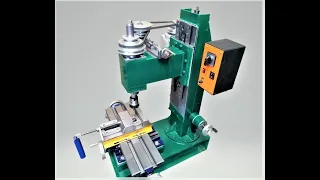
yard. First we will remove the tailstock and tool holder. The middle frame is made of 80mill
imeter aluminum profiles with two braces for greater rigidity. A back plate is added that can be fixed with four screws. The back plate has 4 rollers that fit into the profiles. The back plate can be moved towards the back. left and right using a lead screw the milk uses a Morris chuck that I bought on eBay.
It can hold drill bits up to 16 millimeters. The mill spindle is supported on tapered roller bearings which sit in a housing and can be preloaded using a nut. The spindle is driven directly by a 50 volt 500. watt brushed DC servo motor via flexible coupling. Two 15 millimeter linear guides are mounted on the backplate and the entire motor assembly rides on these guide rails. The lower shaft mounting plate can be finely adjusted using four long bolts. The motor assembly can be moved up. and downward by a lead screw with a hot gear drive coupling providing a
vertical
movement of approximately one millimeter for a rotation of the handle by a stop the motor assembly can be set in a fixed vertical position vertical reading is made Using a digital gauge, the motor speed is controlled by a home-built speed controller with Tahoe feedback.
More Interesting Facts About,
building a vertical mill from industrial scrap...
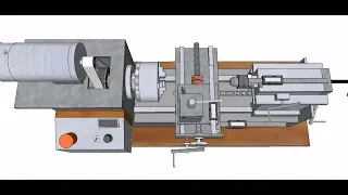
The unit is powered by a 50-volt, 800-watt power supply. The lathe carriage and cross light now serve as a mil xy table. The cross slide caliper moves to the left side and a 20 millimeter thick metal plate is screwed to the thick slide like a vise. I used separate metal blocks that can be screwed in different positions to the table. The movable jaw can be moved with a 20 millimeter bolt. The movement is slightly greater than the distance of the holes in the plate so that any size objects can be clamped. The center line of the mil chuck matches the center line of the lathe chuck, which is useful for drilling holes and milling slots.

On the parts that are clamped in the lathe chuck for this purpose I mounted a dividing disc with 48 holes on the lathe spindle. The back plate assembly can be moved 25 centimeters horizontally and the motor assembly can be moved 35 centimeters vertically. xy table can be moved 25 centimeters in the x direction and 20 centimeters in the y direction, which is pretty good for such a small unit, the total weight is now around 100 kilograms. I can still slide it to the side of my workbench when not in use. The aluminum profiles were cut to size and bolted to the lathe motor housing and back plate. 90 degree brackets and T-nuts do it. easy to slide and adjust the horizontal beams the braces were made of eight millimeter aluminum and fit perfectly into the profile slots they were threaded and screwed to the profiles at the top and screwed to the back plate and motor housing at the bottom Bottom the construction is now robust and rigid here you see the set of tapered roller bearings of the chuck spindle and bearing housing which came from an old pick and place machine.

The motor casing was made of 12 millimeter and eight millimeter aluminum. I used my router to router the sides of the plates. here I am cutting the hole for the bearing assembly. I am using the holes in the bearing housing as a guide to drill the holes in the plate. The motor casing is almost finished. Now we can mount an axle, add the spacer and tighten the nuts. To adjust the bearing preload, the flexible coupling can also be fixed. The guide rails slide inside the blocks. Here you can see the vertical stop with the T-nut that will hold the backplate.
The backplate is also made of eight-millimeter aluminum. It can be attached to the profiles with bolts and T-nuts. Here I am drilling and tapping the holes for the guide rails. I used my router and guide rails to mill a slot in the back plate for the vertical stop, the back plate and the guide rails should be perfectly square to the base of the lathe. Here I am turning the aluminum rollers for the back plate. I'm turning all four together making good use of my home built lathe. The final result looks pretty good. The bearings fit well in it. rollers which are then screwed to the back plate the height of the roller can be adjusted to fit the profile slot now the motor assembly can be screwed on and the stop can be mounted the lead screw assembly which moves the motor assembly also came from the junkyard The brass nut is screwed to the side of the motor housing and the lead screw drive box and top end bearing are fixed to the back plate.
The lead screw that moves the back plate is made of an m12 threaded rod. I had to twist one end down to fit. the bearings and tap an m8 thread into the end of the rod here is the final result now I am turning the bearing housing and drilling the holes for mounting the bearing housing. I made this jig for drilling straight holes in the profiles which works quite well after assembly. On one side of the bearing housing I mounted the lead screw assembly to have all the components in line, then added some cyan glue to the bearing housing and profiles.
Now I can drill the holes, tap the thread and put everything back together and then we can put it back together. The back plate assembly on the aluminum frame can be fitted with a square nut and holes can be drilled, then the nut is screwed to the back plate and the assembly can be moved by the lead screw. The power supplies I used also came from the junkyard. I think they come from old telecommunications equipment. They have a 12 volt output and an isolated 48 volt 7.8 amp output. I placed two units in parallel to get about 800 watts of power.
These supplies are designed for forced cooling, so I added two fans into the holes in the case. use some mesh cloth to keep dirt out. The end result is a nice compact housing that fits on top of the grinder. Here you can see the speed controller circuit, which you can also download from our website. The two power supplies are paralleled by balance resistors. The power stage is similar to the speed control on my Tahoe lathe with feedback and an OLED display. I also added motor current detection which is then displayed as torque on the screen. I used the isolation routing method to make the PCB draw the component locations and copper traces by hand. 0.1 inch graph paper, then I lead-punched the holes for the components, then covered the top with marker ink as a background for the carbon paper I used to transfer the copper design from the top to the PCB and then I used an engraving tool with a fine dental milling bit to cut the copper and form the copper islands, this process is repeated for the bottom part, finally we need to make sure there are no short circuits, some layer holes top must be insulated from the copper of the top layer.
In this design, the two power components are mounted on the bottom plate of the case for cooling. Now we can solder the SMD components on the top and bottom, then come the removed components and finally the power components are soldered in place after a bit of programming we got a working speed. controller before final assembly, everything has to be well aligned. Here I make sure the aluminum frame is parallel to the base of the lathe. After putting the backplate assembly on, I'm adjusting the rollers to make sure the motor mounting rails are square to the lathe bolts.
You can also tighten the lathe bolts and check that everything is square again. If all is well, the centerlines of the chuck and lathe trap are perfectly aligned. The power supply can now be mounted and all cables can be mounted to the speed controller. It is necessary to connect it, including the tahoe feedback cable and the front speed control panel. When everything is wired, we can turn the main switch dial to the required milling speed and flip the switch. Let's try the torque reading. I set a lower rpm and try to slow down. By lowering the chuck by hand, I can see that the speed remains constant but the torque reading increases due to the increased motor current for the indication of the vertical movement of the mill.
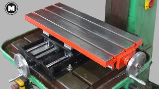
I am using another digital caliper that is mounted on an aluminum block with a slot. A bracket is mounted on the side of the motor housing and the gauge block slides over the bracket The other side is fixed to the motor housing Vertical movement can now be checked accurately and zeroed at any position is now the time to assemble the mill table The first nine holes are drilled in the cross slide plate, the gauge readings allow the holes to be drilled very accurately, then drill the center hole of the mill table and then use the holes of the cross slide plate as a guide for drilling the holes of the mill table, which achieves well-aligned holes.
Now we can start milling the sides of the milling table. This is the first use of the mill and it seems to work well with light cuts to dress the surface of the router table. First I build a kind of fly cutter. I fix the spindle of my lathe. With the dividing wheel I can now mill a slot in the round piece of metal that will hold an SCMT carbide insert. The slot milling looks good. Now we can rotate the shaft of the fly cutter. Here is the end result. I decided to mount two inserts for balance.
I first tested the tool on a piece of scrap metal to see how the fly cutter works. The surface finish looks good, but there are clear steps on the two adjacent passes. This is because the milling head is not completely square with the surface of the lathe base. I check this with a dial indicator on a glass plate. The milling head plate can be precisely adjusted with the four long bolts. It took a little effort to get the milling head right, but now the indicator shows that it is perfectly square in all directions. Milling head bolts.
Now it can be tightened let's try some service passes again. There are no more steps between passes, so now we can mill the surface of the router table. The end result is a perfectly flat serving table. I originally planned to mill T-slots into the table. but some tests showed that it is very time consuming this 15 millimeter T slot milling took about an hour so I decided to drill holes every 14 millimeters and rows of holes 60 millimeters apart the hose method will also keep the table More rigid compared to a T-slot table, the Thread the M8 into each hole first using the mandrel mill to start the thread straight and then finish the tang by hand to the center vise.
I found a tool steel bar at the junkyard that was nice and square on all sides. I cut it with a grinding wheel before I could mill it. I needed something. to attach it to the mill table, so I made these simple low profile clamps from scrap, first cutting the slots with an eight millimeter mill, the result is not that bad, milling the front surface, now it is necessary to drill the holes of strain relief and then the sides can be drilled. It can be cut and the vertical slots can be cut. It takes a little bit of top milling, which gives me a little more practice.
Holes for the clamping adjustment bolts can then be drilled and tapped. Here you can see the final pieces. First we mount the low profile fixed jaw on the table and make sure it is parallel with a gauge now the part can be clamped to the table using the other movable jaw after tightening the bolts the part is well clamped now we can start milling the rough cut surface of the fixed jaw of the vise and after drilling The holes, the recessed slot for the bolt heads, can be milled with a 30 millmillimeters. Now the final jaw can be screwed to the table and adjusted so that it is parallel and we can finish the other pieces.
Here I am drilling the holes. the rods, which must be very precise on all the pieces, finally I use a 12 millimeter reamer on all the pieces, then we mill the slots a little more and tap the m12 thread. Now the pieces can be assembled, as you can see, the rods fit well and the whole slides perfectly. straight and flat on the mill table it would have been very difficult to do this with my simple bench drill. Let's use the vise to hold a 60 millimeter aluminum block after positioning and screwing the movable jaw assembly. The movable jaw can be pressed against the block.
With the M12 bolt, the block is securely fastened. Now let's hold the block using high parallels. After tightening the jaw, one of the parallels is released. This is because the movable jaw tends to lift when the block is clamped on the top of the jaw to overcome. This I can use the two bolts to attach the moving jaw to the table surface. Now the block sits nicely on the parallels again. Let's make a 28 millimeter cube with this 30 millimeter square aluminum bar. First I cut 30 millimeters in length with my circular saw. I am using a milling method that I learned from joe posinski's youtube channel.
First we need to make the square block, the milling depth is around 0.7 millimeters. This milling direction and sequence gives almost no origin, we can now make a light pass around all the edges and then the other side of the block can be milled using the same milling direction and sequence as the top and bottom surfaces are now parallels. We can clamp them directly in the vise. One of the milled sides sits in a single low parallel. Now we can mill all four sides. Using the same sequence after all four sides have been made the block is now square, we still need to mill to final size.
Now we can use two parallels to hold it. I need to remove about 0.61 millimeters from one side, so I set the milling cutter. the surface zeros the caliper and then sets the milling depth to 0.55 millimeters to make sure I don't go over the final size of 28 millimeters after milling this surface, let's check the dimension again almost there, I increase the milling depth another three hundredths of a millimeter and Make another pass, now we should reach the final size to be able to mill the other surfaces also with the same milling depth. The final dimension is pretty close to the target.
Not too bad for a first test. One of the things I learned from this build is that rigidity for a mill is even more important than for a lathe. This lightweight construction is, of course, not as rigid as these heavy cast iron machines, but for soft materials and light cuts, this mill seems to work quite well. It takes about five minutes to convert from mill to lathe, so it's quite convenient. I spent about 350 euros on this build, which is not too much. Bad, I put some of the design files from this build on my website. Please see the description below for more information.
I hope you liked this video. Thanks for watching.
If you have any copyright issue, please Contact