SPMT SCHWERLAST-SELBSTFAHRER - Transportwunder mit Megapower | WELT DOKU
Mar 10, 2024The miracles of self-propelled transport on wheels They are off-road professionals, whether on difficult terrain or on steep slopes and descents. They are used where other transportation systems fail. Self-propelled vehicles carry loads up to seven times their own weight for many chassis together, they are true giants. No problem, the transport vehicles have huge engines with more than 500 HP and an exceptional chassis with eight wheels per axle line. Its great advantage is maneuverability, whether driving sideways diagonally or turning on the spot. The headquarters of Goldhofer AG in Memmingen, Bavaria, on an area of more than 100,000 square meters, the expert in special vehicles with around 800 employees, transport systems of various types, semi-trailers, trailers, low loaders, tractor units for aircraft, as well as transport modules without and with their own Propulsion, the so-called self-propelled transporters, that is, self-propelled vehicles, which consist of two large components: the propulsion module, also called the power unit, and the chassis, which has the 6-axle chassis vehicle.

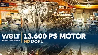
This 48-wheeled vehicle can carry enormous loads of up to 235 tons, although it itself only weighs 26 tons. The attached engine weighs another 8.6 tons, in which a gigantic six-cylinder turbodiesel is installed that produces around 530 HP. displacement of 12 liters and develops a torque of approximately 2100 Newton meters the frame for a propulsion module 5 meters long, three meters wide and 86 cm high reaches the transport warehouse, where the installers have to turn the colossus of 2.6 tons manufactured Only then can the individual parts be used upside down. Assembly for the drive The core of the drive is the six-cylinder diesel engine from Deutz, which takes just under a ton to assemble.

More Interesting Facts About,
spmt schwerlast selbstfahrer transportwunder mit megapower welt doku...
So the installers placed the engine on a non-Deutz mounting bracket and put consolidation protection on it. To prevent it from rusting, of course we have to do it at the front and then we build it up gradually. Our components, gearboxes, pumps, etc., take care of the conservation at the installation points with brake cleaner. It is also important to mix the threads and that they are absolutely free of grease, oil and dirt due to the immense vibrations. The fixing screws are also glued to the engine. The first fixing element is the clutch, specifically the clutch driver. A special adhesive is applied to the fixing screws, first tighten the screws with the impact wrench and then start. with a torque wrench on the powertrain frame.

The installers are now working on the hydraulic system pipes, since the self-propelled vehicle is not driven mechanically by a cardan shaft, but hydraulically, that is, with oil pressure. Propulsion vehicles are also called hydrostatic propulsion tractor modules. The hydraulic drive allows continuous and jerk-free driving both forward and backward. The hydraulic tubes of the powertrain have a pressure of up to 420 bar. They have a diameter of 8 to 100 kg. 42 mm and a wall thickness of 1.5 to 3 mm. The hydraulic control is already pre-assembled. It can be controlled manually or by remote control. Mechanics now mount the hydraulic tubes to the valves and pressure connections.

The line with the marker means re-torque on the engine, not a normal gearbox is installed here, but a pump transfer case. Stefan Kollmus sprays the threaded joints with metal protection. He then lubricates the driveshaft and places the clutch damper in the transfer case. He screws in the clutch damper and then checks to make sure everything moves smoothly. He can now attach the transfer case to the engine. The motor generates rotation and the rotation is redirected through the pump timing gearbox to three outlets in which three outlets where the pump is flanged at the bottom, there are two displacement transmission points at the top , a pump running and the rotation creates the pressure. , the travel drive pressure at the bottom and the working pressure at the top The travel drive points are solely responsible for driving the axes.
The working points generate the pressure to raise and lower the self-propelled vehicle. various directions using a radio remote control for the chassis and steering. This means the driver can step on the accelerator, twist the brakes and raise and lower the chassis. Various self-propelled vehicles can also be controlled with the radio remote control. at the same time synchronously, as happens here in an open-pit mining operation in Saxony. A drive station for a conveyor belt system must be implemented, because the steel monster is almost 50 m long. Heavy duty experts have to transport it. With two radio-synchronized self-propelled vehicles, four and eight axles are needed for a total transport weight of 130 tons, as the axle load increases.
The maximum weight on public roads is 12 tons. Self-propelled vehicles have four- or six-axle lines. The structure is basically rectangular in section with integrated air and hydraulic oil tanks, which makes the chassis resistant to torsion thanks to its stable cross members and reinforced outer areas. The motto is to maintain the lowest possible dead weight and the highest possible load capacity: the frames of the 6-axle model weigh 11 tons. The installation of the hydraulic system in the new steel colossi measuring one meter long and three meters wide is extraordinary. Various components have to be connected with different lines. Now we come to the hydraulic regulations for the level steering and travel transmission, the level lines are for 7 and below, then we have the steering, the steering block is controlled through the steering and the.
The travel transmission is the big lines for the hydrostatic transmission. Here is a nitrogen storage to intercept the tip and direction. Here it is necessary that if the hose breaks, the vehicle cannot descend. Hello, the pipes were previously bent exactly as planned. Now installers have to cut them to exact length. The hydraulic pipes for the drive have a wall thickness of 5 mm, as they must withstand the highest pressure, i.e. 420 bar. Now you have to deburr the interfaces and widen the ends of the tubes. Outside and inside, the installer widens the tube by pressing a conical sealing nipple.
The tube is now so bent at one end that the gaskets and fixing nuts can no longer slide on it. , the tube bends. The installer opens the other end of the tube. Finally, a lubricant is applied to the joints. Then the installer can use the hydraulic cable to drive. Using the nuts, pull the ducks of the bent tube inward and. External thread seals Connections are tight after tightening, even with huge threads. The pressure is 100% tight, the power unit frame has now been painted, including the hydraulic system, to protect it from corrosion. For all additional components, electricians are used.
They lay a large number of cables with a total length of several hundred meters, install control units and connections, among other things for power supply and electronic control of fuel supply, exhaust gas cleaning and cooling, the completion of the 530 HP engine for the drive group, the pumps for the drive and the working hydraulic system are already installed, as are three of the huge hydraulic hoses. As soon as the remaining hoses are connected, it will now be the 1st. The .6 ton engine is ready to be installed in the painted frame of the chassis, the pneumatics for the braking system and electrical are already installed.
Here we can now see that all the electrical cables have been routed throughout the chassis. They are centralized in our control boxes. Switch boxes are responsible for controlling the direction. Compressed air is drawn into the chassis through these three pneumatic couplings which then lead to hoses that lead to the valves and the valves are responsible for braking the chassis. Locksmith Jürgen must carry out the following steps on the chassis. The taufratshofer turns the frame upside down to protect the paint, attaches steel spacer bolts with a rubber mat to the chassis of the self-propelled vehicle. The frame, which now weighs 12.4 tons, is made in three stages.
In step 1, the crane hooks are hooked in the middle, after lifting them the trestles are removed, the frame is placed with the insensitive side on the ground, in step 2, the men hang the frame. The kickstands with their steel-reinforced rubber pads are on one side of the chassis and are held in place with extensive damage. The chassis hangs vertically, moves back and sits on the spacer bolts. Locksmith Jürgen Taufratshofer places the steel. -reinforced rubber pads on which the undercarriage is temporarily stored. In the third step, the cars are hung in the center of the undercarriage. Now the installer can install the next chassis component: the turntable for one of the axles. composed of an outer and inner ring and a helical gear.
It is a core component of the multi-directional electronic steering of the self-propelled vehicle. This allows for a steering angle of 135 degrees in either direction. In a rotating ring gear, the shaft moves to the right or left depending on which of the two hydraulic lines the pressure comes from. Before assembly, locksmith Jürgen Taufratshofer cleans the underside of the rotating crown so that it fits exactly the same on the chassis. If dirt gets into the hydraulic oil, it can damage the entire system. The inner ring of the rotating ring gear is now bolted to the shaft. Chassis frame The slewing ring must be firmly seated, so the 24 screws are tightened with a torque of 220 Nm.
Sven Stoffel is responsible for installing the hydraulic pipes. He first connects both axes of a line of axes at the same time. He mounts the two hydraulic hoses from the first axle to the control block. This one has a magnetic switch. Determines the right or left rotation of the shaft by giving the oil pressure to one line or the other. He screws the ends of the hoses together. The hydraulic pump that drives the worm screw. Now Sven Stoffel has the hoses for the opposite axle and connects them to the hydraulic block that controls both axles, so the opposite axles rotate in exactly the same direction. in exactly the same direction Opposite direction Multi-directional electronic steering makes the self-propelled vehicle extremely maneuverable.
Each axis line can be controlled individually. Even tight turns are no problem, no matter how big and heavy the load is. Sven Stoffel installs a so-called leak oil line on the hydraulic motor. Return excess oil to the tank so that the pressure in the engine does not rise too high and destroy it. The power supply is now ready for installation. Large Components Installers have already installed many smaller components. Here we have the lifting cylinder, the locking cylinder to install a chassis, which goes further and further. The air tank for pneumatics. Here we have already installed the control cabinet.
If you look inside, we have. two batteries and a distribution box and here the pneumatic brake then here we have the exhaust gas level door at the end where there is combustion twice and once in injector 1 if the exhaust gases are not correct they burn at injector 2 and then it is measured again at the outlet and if the exhaust gases are not correct, the machine turns off. Two other important installations are the AdBlue tank and the two engine control devices. A huge machine also needs huge refrigerators. The self-propelled engine also has huge. First, mechanic Hugo Kiechle lifts two of them into the double cooler for the hydraulic oil.
It has a performance of 140 liters per minute, 100 liters for the translation system and 40 liters for the working hydraulic system, that is, to raise or lower the chassis. while the mechanic screws the cooler and assembles the Maxbär hydraulic system the connections: the lower one is the oil drain, the upper one is the inlet, a hydraulic motor drives the fan. On the right is the pressure connection. On the left, the oil return. The second largest unit is a combined cooler for the engine and charge air. A flow rate of approximately 400 liters of water per minute is installed in the combined cooler.
They are the heart of the engine, the 530 HP 6-cylinder turbodiesel with a displacement of 12 liters. To lift it with the crane, mechanic Hugo-Kirchle also needs a crossbar, since he has to lift the engine in three places. The only way to get the motor to hang exactly horizontally during the stroke is to fix it to thechains in separate places. The first attempt failed. The engine is twisted. Hugo Kiechle has to readjust and shorten one of the chains. The second attempt was successful before the mechanic maneuvered the engine to the power unit. He still has to unscrew it from the mounting stand with all the accessories on it, the engine now weighs 1.6 tons plus the carriages and crossbar.
Great care must be taken when lifting the engine. The engine in the powertrain Damage to the machine or other integrated parts would not only be very costly but would also make it overcrowded.The last meter and a half of the timed production process is completely done. Now we also need to make sure that the powerful hydraulic and cooling water hoses are in the correct position and that no other parts are damaged. centimeters is delicate work with crane control Hugo Kiechle pushes the engine mounting bolts and presses Adjust the engine with muscular force so that the bolts thread into the holes in the frame, the engine is seated and the mechanic now has to tighten the screws below.
Power unit in supine position Preparation for installing the axle in the chassis Electrician Marco Kühnel installs a potentiometer on the worm gear of the rotating ring of the axle, which is a mechanically adjustable resistance If the worm gear rotates, the value of The resistance changes and therefore indicates the angle direction of the axis. The second and fourth axles on each side of the module are driven with hydraulic pressure and braked by pressure reversal, the module moves forward or backward. This shaft is a non-driven one that needs it, therefore it is compressed. The pneumatic brake, which weighs more than 500 kilos, can be adjusted in height using a hydraulic cylinder.
Now the electronic control cables and hydraulic hoses should be out of the way. shaft in the rotating ring and align it precisely for fixing Jürgen taufratshofer inserts 30 screws into the holes and tightens them first with the impact wrench and then with the torque wrench. The axle must be 100% secured because it is subjected to extreme loads. its multifunctionality The axle has a total steering angle of 270 degrees and has a hydraulic compensation of 30 cm Up and down there is a compensation of the axle when passing over an obstacle, you have to understand this: the axle moves over the obstacle, the axle . it retracts and after overcoming the obstacle it comes out again, of course on the road, so the loading area remains at the level another function The axle can oscillate, which means it compensates for irregularities in the driving surface.
When used on difficult terrain, the combination of level control, axis compensation, steering angle and oscillation is especially important, since in the case of transporting a conveyor drive station for open pit mines, the displacement of the load under this conveyor belt requires millimeter work. This is only possible because the driver of the two self-propelled vehicles lowered the chassis completely, i.e. 30 cm. Otherwise, the heavy transport would have touched the conveyor belt and possibly destroyed it. Another challenge in this transport is the curves with such a tight radius than the self-propelled one. The powered vehicles have to carry the 50 meter long load.
Inside the curve on the unpaved shoulder, in self-propelled vehicles, each axle maintains contact with the ground thanks to the hydraulic compensation of the axle while the transport surface itself remains horizontal. The next curve also has a slope and a side slope. Fewer off-road transport vehicles would overturn here. Self-propelled vehicles rise. The axles on the inside of the curves touch the transport surface and on the outside of the curves the axles oscillate. the unevenness. This turning maneuver is successful in tight spaces without maneuvering only thanks to the enormous individual steering angle of the axles before the wheels have to reach the chassis axles, if the materials are the hydraulic system.
To check it, first connect. the leak oil hose that drains excess oil from the hydraulic motors, then the pump line, i.e. the oil inlet, and finally the return hose to the hydraulic tank. In this test, all hoses lead to a hydraulic unit. pressure of 100 bar, so I turn them all on. Axles to check the direction of rotation and the tightness of the hoses. Sven Stoffel is now testing four axes at the same time for accurate and synchronous turning. All axles rotate in the same direction as it fits. The block is tightened and now we have an axle all the way to the stop.
The stop is purely a safety device because normally a potentiometer measures the angle of the axle and limits it to 135 degrees left or right. Sven Stoffel checks if there is no hose. pinched, then check with a mirror if the end stop has been kept on the right side, everything is fine, then you turn the shaft in the other direction, it's great if the end stop is not kept, the bend of the shaft will be cleaned towards the center. , it would spin permanently and all the hoses would break. Tire tire Markus Treffler is now testing compressed air brakes on non-drive axles.
These are the three problems in compressed air connections. The compressed air tanks were filled, this is the service brake clutch and, through a necessary duct, we have several chassis in a row, but braked in half, Markus Treffler subjects the pneumatic system to pressure with 8 bars, he says . connects it to the one in the frame built-in storage tank a pressure gauge first tests the parking brake comparable to the handbrake in a car by pressing the brake release button, pressure is applied to the parking brake spring accumulator the spring contracts the parking brakes should now be released, the tire has to do this for each of the 8.
Check the axles individually, they are all free, then the parking brake should be closed. Here again, the individual verification on each of the pneumatically braked axles. , now I know the brake is working properly and now I'm testing the service brake so I press the button The parking brake is on and now I'm here with a new connecting piece in blue for the service brake and the brake. now with a 6 bar brake and now all braked axles should be tightened again, this should now also be firmly checked again and the compressed air hose should be removed again and then everything should work, so that both the brake parking as the service brake now set Markus Treffler.
Press the service brake again to close it, then remove the pressure hoses and test if the system is tight overall, then we rest for 10 minutes and make sure we don't lose pressure. The result of the tire. The braking system is absolute. In some transports, self-propelled vehicles also have to overcome extreme slopes. The double braking system provides additional safety. Non-drive axles brake pneumatically, that is, with air pressure. The drive axles are braked hydraulically, that is, by throttle. Oil pressure. The drive axles do not have enough grip. Sometimes they even rotate backwards under the power pack assembly. They are made of aluminum to save weight.
The largest tank is for hydraulic oil. liters At the top there is a filter for the transmission oil and the working hydraulics mechanic Hugo-Kirchle connects the level indicators that the electricians will use later. There are still pressure relief valves on each of the. Two parts of the tank, similar to those of a car radiator, open at 1.5 bar and release air when the hydraulic oil expands due to heating. The temperature sensors that the mechanic places in the filters measure how hot the oil is. The oil tank is a complicated matter, because the powertrain is now very tight.
Collisions with other integrated parts could cause damage, which in turn could mean mechanics having to disassemble the powertrain again. Lines and screws by the mechanic Hugo Kiechle. The hydraulic oil tank is closed tightly from below and then the sight glasses are fixed to the side, the optical level indicators in case the electronic ones fail, the next installation part is the air intake system, including the fuel filter. air, for the enormous six-cylinder diesel with 12 liters of displacement and torque of 2130 Newton meters. Such a gigantic engine also needs a corresponding amount of engine oil. The tank has a capacity of 60 liters and has blue connecting hoses so there is no confusion with the hydraulic oil lines.
It is followed by part of the propellant with a capacity of 450 liters because it is a Deutz engine. With 530 HP, consumption is relatively high, from 10 to 70 liters, although there is no maximum limit. Depending on what is loaded, consumption is corresponding. Of course, especially on long uphill journeys with many curves, consumption increases considerably, as is the case with this transport of a 50 m long wind turbine blade in the Black Forest. -The powered vehicle must ascend 400 meters in altitude with slopes of up to 20%. The transport, which weighs a total of 85 tons, consumes 280 liters of diesel every 100 kilometers over the 7 kilometers, including numerous maneuvers, which would mean a volume of 4,000 liters.
The 6-axis module of the self-propelled vehicle. Precisely, six lines of axles, each of these lines consists of two rotating and orientable axles, in each of them 12 individual axles are mounted on four wheels. This chassis has 48 tires. Each tire weighs a little more than 50 kilograms. It weighs 5.6 tons fully loaded. The pressure on the tires must be high so that they are not too strong under load. For safety reasons, filling with 12.6 bar is carried out in a steel cage because if one of the tires bursts due to a defect. , bystanders could be injured or even killed. Four wheels are mounted on each axle on the inner wheel.
Locksmith Jürgen Taufratshofer uses a valve extension and then lifts the crane onto the axle and threads the holes into the inner wheel bolts. bolted to the outer wheel, the locksmith had to tighten the ten wheel nuts with a torque of 650 Nm. To do this, after mounting two wheels on each axle, he used a special high-torque wrench with counter support. Meanwhile, locksmith Jürgen Taufratshofer screws two consoles to the sides of the chassis, with which the chassis must rotate once all the wheels are mounted. move from the supine position to the normal position. The locksmith removes the safety bolts from the axles and lowers them hydraulically.
The chassis is rotated in stages. The locksmith fixes the sickles with threaded shackles. Steel reinforced rubber mats in front of the newly installed steel consoles. Using the crane, lock onto the chassis, consoles, and support blocks until it is vertical, then lift it up and drive it to the edge of the room. Now tilt the chassis back onto the supports at the front and rear ends. The next step is to reassemble the illnesses from the side to the center of the chassis. Then it's time to pick it up again, remove the stands, and lower the chassis to the ground.
The six-axis module is now ready. With a dead weight of 26 tons, it can transport up to 235 tons. Several docked modules can lift much larger loads, such as here in the port of Altinova, 50 km southeast of Istanbul. Two newly built Norwegian passenger ships that the heavy company Haaricke must carry one after the other from dry pressure to the pool each weigh an impressive 6,200 tons. These steel monsters are 124 meters long, 22 meters wide and 35 meters high. To transport them, 200 lines of heavy axles with 1,600 wheels are used. Fast travel is not possible with repeated maneuvers, transportation requires four full days for a distance of only 250 meters, so the two giants are just one and one.
In the pool, half a meter away, both components of the self-propelled vehicle are already finished. Now Sven Stoffel has to check if both. The tank also works at 100%, the vehicle already runs on diesel and now I will refill the hydraulic system. The tank holds 1,130 liters of oil to put it into operation. The power supplies are always filled using a filter so that we can detect possible particles or debris in the oil tank, since the pumps are very sensitive to dirt. Now 40 liters per minute. flows into the hydraulic oil tank of the generator set, filling takes about half an hour Sven Stoffel starts the six-cylinder diesel engine with a power of 530 hp and checks whether the number of revolutions is set correctly and whether there is enough oil pressure in each of the systems with the pressure supply, the hydraulic pumps of the engine itself are put under pressure.
It has to be between 28 and 38 bar. This will begood. Next, check the play oil pressure. It is used to cool the wheel motors that drive the axles. A little less than 25 bar. Also okay, I like the pump pressure 50 bar and then the brake pressure for the new chassis, now the brake pressure is no longer necessary, but if the customer has an old chassis that is going to be driven. Combined or alone, you need this brake pressure again to activate the hydraulic brake and also the pump pressure. The drive of the axes is correct, as is the working pressure.
It is used for steering and raising and lowering the chassis. The working hydraulic system also drives additional equipment, such as a transport device for rotor blades. This rotor blade for a wind turbine in the Black Forest is 46 meters long and weighs around 15 tons. The crane driver has to screw in the 72 rotor screws. blade into the holes of the blade rotation device, but it rarely works with 100% accuracy, so when transportation manager Randolph Peters uses a trick that uses the adapter to make the threaded rods of the motor blade can easily insert into the adapter and now screw them together at 72By connecting the rotor blade with the wing carrying device, the journey begins with a remote control, Randolf Peters can not only turn and accelerate, but also rotate the rotor blade around its own axis and raise it 60 degrees upward.
Sharp turns in the mountains can be made with your vehicle without the rotor blade hitting anything, even extremely narrow spaces like in this group of houses can be overcome with the self-propelled vehicle. Randolf Peters lifts the rotor blade using a hydraulic system and then rotates. In doing so, he lifts the self-propelled vehicle on one side and, through this bottleneck, returns to the Goldhofer factory in Memmingen. The next step during start-up of the self-propelled vehicle is to check the refrigerator by short-circuiting an electronic sensor that simulates overheating. The refrigerator fan must start and reach at least 3100 revolutions per minute.
On one of the fan blades there is a reflector that measures the number of revolutions of the fan with a scanner. The result is that the refrigerator is now working. Sven Stoffel can mount the 8.6-ton powertrain into the chassis, perform the so-called wedding with his employee, push the hydraulic hoses through the openings in the chassis so they don't get stuck, and then fine-tune them until they pop out. coupling are exactly aligned and the lock the bolt passes now it is the turn of the hydraulic cylinders of the power unit now we install the lifting cylinders so that the power effect can be tilted and does not rest on slopes Sven Stoffel now screws the cylinders hydraulics to the chassis with fixing The pressure hoses and union are complete and testing of the working hydraulic system can begin.
First, Sven Stoffel checks whether the powertrain can be raised and lowered from the front, then he checks the chassis, raising and lowering it in all directions. Everything works perfectly. This working hydraulic system is necessary, especially when used on uneven terrain like here in the Black Forest. When reversing, this self-propelled vehicle has to go through a depression with its load. The hydraulic system ensures that the transport surface remains horizontal. At the Goldhofer factory, Sven Stoffel has installed a driver's seat in the chassis. He needs it for the first test drive. Its measuring instruments show whether the self-propelled vehicle moves with a given pressure in the hydraulic system.
This is especially important when several modules are coupled together or when several self-propelled vehicles transport a large load together, so reverse second gear at maximum speed 15.3 at 154 bar perfect forward first at maximum speed 66 bar at 4.0 and back at 67. bar perfectly, so after the test drive everything is fine, the speeds are correct, the pressures are correct, I have no flats, the vehicle speed is completely fine, now there is a emergency stop brake test, yes, and then that's it. In fact, the vehicle has completed the emergency stop test with Sven Stoffel's radio remote control since its commissioning. He starts the self-driving vehicle and then presses the emergency stop button at full speed, which means the emergency braking works. perfect In places where support wheels were previously mounted or where paint damage occurred during assembly, there are eyelets on the sides through which tension chains can be hung, for example, to secure the load.
The cover plates of the generator set are non-slip. Powder coated aluminum plates. Two employees from the finishing department assemble the bumper with integrated headlights and indicators and then connect them to the electrical network to avoid confusion. There are also stickers on the numerous connections for hydraulic, pneumatic and electrical systems. The self-propelled vehicle is now ready. The final engine and chassis test. The lower part has a load of 30 tons of concrete. Coach Daniel Beyer has loaded it to the max. The six-axle vehicle transports 235 tons. Daniel Beyer first tests the steering and runs the preset programs. First, circular driving is possible, which is possible by turning the three front axles in the opposite direction to the three rear ones.
Offset and crab steering In the following steering program, the front axle is 90 degrees to the rear, the steering angle is reduced, and the rear axle is strong; The so-called wiper operation, once the steering programs have worked, represents another obstacle. For the forklift driver to test the hydraulic compensation of the axles. The different axles raise when going up and lower when going down. Finally, it is checked if the axles rotate correctly to overcome the obstacle. with only two of the axle wheels The pendulum axles compensate for irregularities as intended. Everything works. The self-propelled vehicle can now be delivered to the customer.
The price of the 6-axis module with motor unit included depends on the respective configuration. is in the high six-figure euro range
If you have any copyright issue, please Contact