Making logic gates from transistors
Mar 28, 2024So this little one that I have here is a transistor and the schematic symbol that represents it here is this diagram here and you can see, to get your bearings, there are the three wires in the transistor and those correspond to the three things here, so We have a emitter, a base and a collector and just to orient ourselves, this would be the emitter, the middle wire is the base and this wire is the collector, this is how this corresponds to the schematic symbol and what The transistor is basically a current switch, what that means is that if we set a current from the base to the emitter in this direction, that will turn on the transistor and the transistor will allow a much larger current to flow from the collector to the emitter, so what we can do with that is something like this , which is the circuit that we have set up here and basically what this circuit does is we have a switch that allows us to complete a circuit that allows current to flow. like I said base to emitter base to emitter so if we close this little switch we press this button which sets up a circuit like this and causes current to flow from the base to the emitter which turns on the transistor once the When The transistor is turned on, current is allowed to flow from the collector to the emitter in this direction and that allows this kind of second part of the circuit to work where the current will flow from the battery here through this resistor through this emitter of light. diode or LED that will turn it on, let's see, it turns on and then through the transistor and then if we are not passing current from the base to the emitter, then it transits or turns off, so this other part of the circuit will turn off. and the LED will turn off so we can see in the circuit the first part of the circuit that we have from the positive voltage rail here we have this resistor that goes through the button and then to the base of the transistor and then that will allow us to make that first current will flow to turn on the transistor and that will come back out through the negative terminal here and once the transistor is on, it will allow current to flow from the positive rail here through the resistor through the LED into the The transistor a through the transistor is now on and then it goes out through this negative rail, so if we press the button, the transistor turns on and consequently the LED turns on.

Okay, so far so good, let's take a look at another circuit that's on the other half of this one. red board here and in this circuit we have something a little different, we have the transistor off but with the transistor off we have this part of the circuit here that actually allows current to flow through this resistor and then through the LED, so the LED is already on, which you can see here, so the LED is on right now, but if we turn on the transistor, we'll actually allow current to flow through the transistor here. and that will reduce the voltage potential of this node and therefore instead of having a positive voltage here that allows current to flow through the LED, we will not have a voltage differential between the two parts of the transistor when the transistor is on and then that will actually have the effect of turning off the LED, so if we do that we will see the LED turn off, so in this case we are using this transistor as a switch to reverse the voltage here, so if we look at the The voltage here right now is zero volts because the switch is open and the LED is seeing a positive voltage and then if we turn the switch on, we have a positive voltage here, but then we get a differential of zero volts here across the LED and the LED turns off and this is a little circuit called an inverter and there's actually a symbol for it and that's a little triangle with a circle and there's kind of a truth table for the
logic
, it's pretty simple if the input is off. the output is on or if the inputs are zero we use it as to represent off the output is on if the input is on then the output is off it's pretty straight forward so let's look at some otherlogic
circuits we can make withtransistors
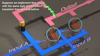
okay the next circuit we're going to look at we have twotransistors
it's kind of like this one on the left half of the board here we have two transistors and the way it works is we have these inputs which again are like I haven't pulled out the whole circuit, but we still have this resistor that comes from the positive rail here through the push button switch and then to the base of the transistor and that allows us to put a current through that transistor and we have two of those and what happens is that if both transistors are on then that will complete the circuit through this resistor here and then through this LED and then you know through the first transistor and then through here and through the second transistor and if both transits are on, both transistors are on, then the LED will turn on and this is a little piece of logic called a NAND gate and this is the truth table for this. the symbol that we would use if we were drawing a more complex logic circuit, we would instead of drawing all the little transistors, we would just draw this whole circuit is just a NAND gate that uses these somewhat rounded symbols. on this side and square on this side and the truth table says that if a and B are off then the output is off and that's what we have now so often both of them don't drive either one or the exit. is off if B is on and a is off then the output is also often we can test that by just pressing the button and the LED is not on the same if a is off or it seems to me that a is on and B is off. then the output is also off, we can test it by pressing the button here, but if both are on then the output is on and that makes sense, if both are on that completes the circuit completely and so on.
More Interesting Facts About,
making logic gates from transistors...
If I press both buttons, you can see the LED turns on because we are completing the circuit. How about this other circuit? It's a little different. First I'll show you the circuit diagram and then The circuit diagram for this is a little bit different, so we still have two transistors, we still have our LED, but they're wired up a little bit different, so in this case the transistors are in parallel so if any of the transistors are on then the LED would turn on because we can complete the circuit through this transistor so we look at the circuit closer here we can see that from the positive rail we pass through this resistor and then by the LED. and then we can go through this first transistor, from the collector to the emitter, or we can go through this transistor through the collector and out through the emitter and then if any of these transistors are on. so the LED will be on so we can test it so if we turn on this one turns on if we test turn on this one also turns on so this is something called gate or so it makes sense if this or this is then the output is on and this is the truth table, so if they are both off, the output is off, which is what we see here, but if one of them is on, then the outputs are on if the other one is on the outputs as well. on and also if both are on because then that will just complete the circuit in either direction and of course in either direction the current will flow and it will be on, so we press both buttons, you can see that it is on in either direction or both.

It doesn't matter, it will light up so you can see here, we have two different circuits, they are very similar, very similar but slightly different, different operation, one is an operation and the other is a u operation, so let's try it, let's take a look at something a little bit more complicated, so this is a different board, here a different circuit and let me turn it on, so we actually have five transistors in this circuit and it's basically the same kind of idea here we have two inputs that we can know, in this case, turn on and off with these little push button switches and we have an output here which is this LED and what we have.

What we have built is what is called an exclusive gate or an is different is that it is off if a and B are on, then we can see that operation, so right now it is off because neither of them are on, but if we activate a, yes, the output is on and if we activate B, then the output is on, but if we turn both on at the same time, the output turns off and to understand how it works, I have the circuit diagram of what is built here and you can see it if we just look at this.
The part here looks a lot like the gate or because we have the five volt source going through our resistor through the LED and that's what's happening here, so we pass the five volt source through the resistor through from the LED and into any of these transistors so it can go through any of these transistors and then the inputs for those transistors are A and B, so these yellow wires come here and then they jump to the switches, so if this or this is on, then that will complete the circuit at least to this point and so at the gate or we just had this connected directly to ground, so if we are on this or this, then that would complete the circuit to ground, but In this case to reach ground we have to turn on this transistor; otherwise you know we have 5 volts connected back to 5 volts and there is no voltage potential difference between 5 and 5 five so the LED is off.
For this or the gate to work essentially, this transistor has to be on and that turns on Esther, actually it's normally on because we have it connected to five volts, so we have current flowing, you know, from the base to the diameter , so normally it will be on unless a and B are on, if a and B are on then this node here will be connected to ground which will turn off this transistor, so if a and B are on then this transistor is off and if this transistor is off, then this or the gate essentially doesn't work, which is what we want to do well, if a and B are on, we don't really want to do the same thing. as a gate or we just want the output to be off, that's essentially what's happening here and that allows us to build, you know, it takes us five transistors to do it, but it allows us to build this other one. logic element which is this frequent, then the output is also off so these are just a couple of the different
gates
that you can build with transistors and here is a whole list of different ones so we saw you know the gate and the gate or We just saw the XOR gate and of course we were looking at the inverter.A buffer can also be created here. I guess that's actually the first thing we did with the transistor, which is that the input was on or then the output. By imposing, the application was not very exciting, but it can be useful and there are a couple of others that we were also able to create and that we did not look at, which are not and NAND, not or and not X. or the X is not called and they are basically the same as the y gate but the output is inverted yes actually if you look at the symbol you have this little bubble at the output, which just means that the output is inverted and that's why it's basically it's the exact opposite, you know that opposite of and other things that allow you to build a computer
If you have any copyright issue, please Contact