Building a Bimetallic Tea Monitoring Mechanism
May 04, 2024We've all been there: absorbed in the task at hand and forgetting about that cup of tea we made earlier. When we think back, it is too cold to enjoy it. Maybe this problem is inconsequential, but, as Richard Feynman eloquently states, "no problem is too small or too trivial if we can really do something about it." With this in mind, let's get to work. Of course, there are simple solutions here, for example we could set a timer, but this is not fun, so I decided to build a complicated
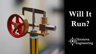
mechanism
that would ring a bell when my drink was at the right drinking temperature: around 55 degrees Celsius .
The
mechanism
is based on a simple scientific principle: thermal expansion. When a material is heated, it will most likely expand. The amount of expansion for a given temperature difference depends on the material and this is quantified by the coefficient of thermal expansion. Here I am preparing two strips of metal. One strip is titanium and the other is brass. Brass has a higher coefficient of thermal expansion than titanium, which is a phenomenon I will explore in this video. By riveting the two strips, their relative tensions couple. I drill the strips and machine some rivets to achieve this.
More Interesting Facts About,
building a bimetallic tea monitoring mechanism...
The resulting structure is known as a
bimetallic
strip. As the strip is heated, brass expands more than titanium due to its higher coefficient of thermal expansion and the strip has no choice but to bend. The greater the temperature difference, the more the strip bends. Indeed, we have a mechanical thermometer, and this is how I intend to measure the temperature of my tea. However, before I start machining the rest of the mechanism, I need to know approximately how much I expect the strip to bend, which can be calculated with this equation. Curvature is a function not only of the coefficients of thermal expansion and temperature change, but also of the thicknesses and modules of the constituent materials.
Once the curvature has been determined, geometric calculations tell us how it relates to tip deflection. Using the materials I had on hand, we were able to achieve a theoretical deviation of around 3 mm for the expected temperature change. When I gently heat the
bimetallic
strip with a blowtorch, you can see it bending. Interestingly, although brass has a higher coefficient of thermal expansion than titanium, the strip can be seen to initially bend away from the flame. This is because I am initially heating the titanium and we get a thermal gradient across the entire thickness of the strip. Okay, so the bimetallic strip works fine, but we need to attach it to the rest of the mechanism, so I get to work making a brass fitting to rivet to the bottom of the strip.
Regular viewers of our channel may notice that the watchmaker's lathe I'm using here is not my usual machine. This machine will eventually replace the other lathe. I am currently working on restoring it. Although it currently looks a bit dirty, it is actually a very accurate kit. I'll show part of the restoration process in a future video once it's all finished. To show the bimetal strip working when submerged, I filled two small cups with water. The orange cup is filled with hot water and the blue one is filled with cold water. When I dip the strip in hot water, you can clearly see that it deviates from the center line.
This sanity check gives me the confidence I need to move on to the next stage. Here I am working on the fitting that will be riveted to the other side of the bi-metal strip. This accessory will accept a probe that will interact with the trigger mechanism. For these small rivets, I am using commercial pure titanium wire, which I believe provides the proper material properties. The material is soft enough to be plastically deformed with a hammer during the riveting process, but still strong enough to securely fix components. So all the components related to the bimetallic strip are now finished and it is time to get to work preparing a brass block from which all the sub-assemblies of the mechanism will be derived.
I have designed this block to attach to the rim of the cup. Here, I am using the rotary table to machine a curved slot in the block, which matches the curvature of the cup. I made the slot wider than necessary to accommodate a variety of different cups. At first, getting a good solid attachment to the cup was more of a challenge than I expected. I intended to make a thumbscrew that would pull the block against the inside of the cup, but as you can see here, the inside of the cup is actually curved, which provides poor registration for the block.
Instead, I had to pull the block against the outside of the cup, which is vertical and straight. To do this, I made a hook-shaped component that pulled on the inside of the cup when I tightened the screw. Of course, we could have placed the thumbscrew on the inside of the cup, but I think that would be too complicated to use. Before moving on to the hooked component, I drill and tap the block for the bimetal strip attachment point and round the top of the block on the lathe to make it more aesthetically pleasing. Now I move on to machining the hook-shaped component from a square bar.
The choice of material is always an aspect that requires consideration, especially in cases of food or beverages. I am making the entire mechanism exclusively from brass, stainless steel and titanium due to their corrosion resistance. While titanium and stainless steel are definitely food safe, brass is more debatable and I would tend to avoid brass in a commercial product that comes into contact with food or drinks. For most of the mechanism I used cz121 and 120, which contain 2 and 3% lead, but for the bimetallic strip, which is immersed in the drink, I avoided lead alloys. Ideally, I would replace the brass with stainless steel in the bimetallic strip, which has a similar coefficient of thermal expansion to brass, but I didn't have any on hand.
The female thread to accept the thumbscrew is manufactured from a separate component, which is then glued to the hook. Science and mathematics underpin all aspects of modern life, but these subjects often have an unfair reputation for being boring or difficult to learn. The sponsor of this video, Brilliant, is helping to change that. Brilliant is an interactive platform where you learn by doing with thousands of interactive lessons in mathematics, data analysis, programming and artificial intelligence. Its courses are designed for students of all levels and are carefully prepared by a specialized team of teachers, researchers and professionals. The best part about Brilliant is that you develop your knowledge through problem solving instead of memorization.
Their short lessons are perfect for learning a little every day, even during your tea break! Some of Brilliant's latest content focuses on working with real-world data to teach you how to spot trends and make more informed decisions. To try everything shiny has to offer free for a full 30 days, visit shiny.org/chronovaengineering or click the link in the description. You'll also get a 20% discount on an annual premium subscription. Now it's time to work on the thumbscrew. I wanted the device to be easy to attach to the cup without the need for tools, so I opted to knurled the screw to allow for easy adjustment between the thumb and index finger.
There are several methods to achieve knurling and to be honest they can be a bit hit and miss on a lightweight machine. Here I use a cut knurling method that removes metal, unlike the more popular knurling method. Both methods have certain advantages and disadvantages, but for this case, cut knurling is a good approach. Cut knurling requires the work to be concentric, so I machine the outside in situ. The knurling tool must be set to the correct diameter to ensure the clearance angles are correct and then the tool is inserted. To be honest, this knurling didn't turn out completely perfect, but I decided it was good enough, so I moved on. on the screw cutting the thread.
On a Myford with a quick-change gearbox, cutting metric threads is easy by replacing a single gear in the gear. When set up correctly, cutting external threads like this is almost as fast as using a die and the result is much better because the thread is perfectly straight and can be machined to fit. At the beginning of the video, I mentioned that the goal was to ring a bell when the drink was at the correct temperature. We considered several approaches to ringing a bell, for example a gravity swing hammer, but Hazel suggested using a ball bearing. I loved this idea and got to work implementing it right away.
We'd love to hear other ideas in the comments, but remember that the challenge here is to cleanly impact the bell once and without dampening the bell's vibrations. For example, it would be necessary to catch a swinging hammer and keep it away from the bell after rebound. Furthermore, the bimetallic strip is very thin and therefore not very rigid, so the trigger mechanism must be actuated with very little force. Here, I machine a tilt ramp like a seesaw. The idea is that the ball bearing will roll down the ramp to the bell when the ramp is tilted. I will balance the ramp so that only the slightest force is required to tilt it.
I make a forked component that sits under the ramp to prevent it from leaning too much in either direction. To machine the rounded section of the fork, I use the rotary milling and dividing fixture I made for the watchmaker's new lathe. Now I start working on the ramp support pillar. This will bolt to the main block to hold a horizontal rod on which the ramp will rotate. I'm making the pillar from two pieces that will be screwed together and then sandwich the forked ramp stop. Here I show cutting the thread with a die. Using a die holder on the lathe tailstock provides an alternative to screw cutting for non-critical applications.
I start with the top component, which is rotated and cross-drilled to accept the horizontal rod. The bottom part of the pillar is a simple twist job, so I did it off camera. The bell is made of a 40mm diameter brass bar. Traditionally, bells are curved to encourage certain modes of vibration. In fact, making bells is a complex and fascinating process. They are usually made from a special bronze alloy and carefully tuned so that the partial frequencies that make up the overall sound are correctly related to each other. This is outside the scope of this video, so I went with a simple machined design with an overall tapered shape.
From an acoustic perspective, this is far from optimal, but it will work quite well here. As I approach the final thickness, the bell begins to resonate. I carefully choose the spindle speed to reduce this resonance during machining. To face the top of the bell after separating it, I use a six-jaw chuck to hold it. These 6-jaw watchmaker's chucks are excellent for clamping thin sections without warping the workpiece. There is only one last component to make before we can begin assembly and that is the part that catches the ball once it bounces off the bell. I start by machining a simple plate.
I start by facing a piece of brass and starting a hole with a milling cutter. Unlike a drill bit, the milling cutter produces a flat-bottomed hole, making it easier to finish the hole with a drilling tool. To join the plate to the rest of the structure, I make a beam that I then glue with silver to the plate. To achieve a good solder joint, I apply flux to reduce oxidation as the metal heats. An oxyfuel torch like this brings the metal to the correct temperature for welding very quickly. This is around 700 degrees Celsius. The welding itself is very fast.
In fact, cleaning is the most time-consuming part of this process. With all the components finished, it's time to see how they all look together, starting with the bimetallic strip. The strip is screwed to the main block using an elbow rod. The crank brings the bimetallic strip closer to the center of the cup, where the temperature of the drink is most stable. This should improve the repeatability of temperature measurements. The smaller toggle rod at the top of the bimetal strip is designed to mate with the ball bearing ramp. The two-piece pillar is then screwed together and the ramp is attached to the pivot bar.
You may notice that I have reduced the length of one of the tips of the forked component. This is to clear the ramp tilt mechanism and because the design is improvised, I initially overlooked it. To hold the ramp in position, I machined two set screw collars. These two subsets can now be joined together. This is the supporting pillar of theCampaign. The cross hole accepts an L-shaped rod that supports the bell and plate. Here, I make the rod into an L shape by heating up some stainless steel and bending it in the vise. The threaded hole in the bell support pillar that intersects the cross hole is multi-purpose.
Accepts both a secret set screw to hold the L-shaped rod in place and the bolt to secure the bell to the plate. The more attentive of you will have noticed that I originally drilled a hole in the top of the bell, but I changed my mind about how the bell was attached to the mechanism, so I drilled it. When I drop the ball bearing onto the bell, it sounds great, but we hear a little extra noise when the ball lands on the plate. Additionally, the ball bounced off the plate. These problems were solved with a magnet and foam pad to catch the ball and absorb any noise as it fell.
Mounting it on the cup is simple. The hook snaps into the edge and then the mechanism. The thumbThe screw is then tightened. To prepare it, the ball is lifted from the plate onto the ramp, but this must be done after the drink has been prepared or poured into the cup. I spent some time off camera finalizing the assembly, adjusting the mechanism and calibrating it so that it is now ready to test. You can see in the timelapse that the bell rings when the water temperature reaches 54 degrees Celsius, which is about right for my taste. To change the activation temperature, the screw under the ramp can be adjusted.
Thanks for watching! If you liked this video, subscribe to see more in the future.
If you have any copyright issue, please Contact