TOP WELDING MACHINE: Mig Welder, Tig Welder, Laser Welding & Robot Welding In Steel Fabrication
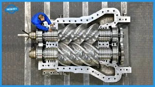
May 04, 2024Hello friends and welcome back to the You Can Do television channel. This is rc80 comprehensive monitoring dual axis friction
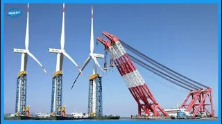
High-quality hydraulic drive system provides more stable power Comprehensive monitoring system monitors, records and stores welding data which can be easily read this video is about submerged arc welding at ARC Energy Resources Limited in Gloucestershire, United Kingdom, submerged arc welding is a joining process that involves the formation of an electric arc between a continuously fed electrode and the workpiece to be welded, a blanket of powdered flux surrounds and covers the ark and, when melted, provides electrical conduction between the metal to be joined and the electrode.
welding
welding
machine
made by jangsu raich Chang Machinery China. Themachine
is designed and manufactured based on advanced design concepts. It adopts a unique interior and exterior. Double body structure to free up more operating space New bridge positioning and clamping device ensures accurate positioning duringwelding
High-quality hydraulic drive system provides more stable power Comprehensive monitoring system monitors, records and stores welding data which can be easily read this video is about submerged arc welding at ARC Energy Resources Limited in Gloucestershire, United Kingdom, submerged arc welding is a joining process that involves the formation of an electric arc between a continuously fed electrode and the workpiece to be welded, a blanket of powdered flux surrounds and covers the ark and, when melted, provides electrical conduction between the metal to be joined and the electrode.welding

It also generates a shielding gas and slag, all of which protects the welds. Welding Submerged arc is seen as a high productivity process and is generally machined in an automated manner in its simplest application. The process uses a single wire. This welding process is generally suitable for the longitudinal and circumferential butt welds required in the pressure vessel manufacturer and for joining plates and stiffeners in shipyards. Welding is positionally restricted and is normally carried out in flat or horizontal positions because of the highly fluid weld pool, molten slag and the need to maintain a flux covering the ark in the grand scheme of maritime logistics, the weight of A ship loader may seem like a mere statistic, however, in the world of heavy industry and port operations, every ton a ship loader matters, an essential component in port infrastructure facilitates the efficient loading of bulk materials such as mineral ores. coal or cement on ships ensuring smooth maritime business operations the weight of a ship loader is a critical factor in its design, construction and installation for a The project in the USA The manufacturing of ship unloader
steel
construction It is a meticulous process that requires precision and experience.
More Interesting Facts About,
top welding machine mig welder tig welder laser welding robot welding in steel fabrication...
The
steel
construction serves as the backbone of the ship unloader and provides the structural integrity necessary to withstand the rigors of continuous operation in a marine environment to ensure. The structural integrity and stability of the ship unloader is paid attention to every detail in the manufacturing process. High-quality steel known for its strength and durability that meets strict industry standards and regulatory requirements is selected for construction. Advanced engineering techniques are used to optimize the design while minimizing weight. without compromising structural integrity in manufacturing facilities. The steel components of the ship unloader are meticulously manufactured and assembled by skilled craftsmen and engineers.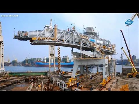
Precision welding and cutting machining techniques are employed to ensure the precision and reliability of each component. Quality control measures are implemented at each stage of the process. manufacturing process to detect and rectify any defect or imperfection. While the final product meets the highest standards of quality and performance, once steel construction is completed, it undergoes final inspection and testing to verify its structural integrity and functionality. Electrical, hydraulic, lubrication and water facilities are meticulously integrated into the steel structure, ensuring seamless operation and optimal performance, the ship unloader is then transported to the assembly department, where it undergoes mechanical assembly and final construction into a complete device during the assembly process.
Experienced technicians and engineers supervise the integration of various components ensuring proper alignment and functionality, a no-load commissioning is performed to test the performance of the ship unloader under simulated operating conditions, verifying its functionality and reliability after rigorous testing and inspection, the Boat unloader is loaded onto a pontoon for transportation to its final destination. Internal transportation logistics are carefully carried out. coordinated to ensure the safe and efficient loading of the ship unloader onto the pontoon, once on board the ship unloader is ready for deployment, prepared to improve the efficiency and productivity of port operations, facilitating the smooth loading of materials to bulk on ships and supporting global maritime trade.
The production line for 76 mm tubes of 60x60 profiles is a sophisticated industrial facility designed to manufacture tubes and profiles with specific dimensions and properties. This is how it works. Feeding of raw materials. The process begins with the introduction of raw materials, steel coils, into the production line these materials are fed into the line through rollers that are formed in the forming stage, the raw material is given the desired profile for a 60x60 profile, the material passes through a series of rollers and dies that gradually bend it and shape it to the required Tu profile, welding the formed Prof file. welding to join the edges and create a continuous pipe, sizing and straightening after welding, the pipe undergoes sizing to ensure that its dimensions meet the required specifications, in addition, it went through straightening machines to correct any deformation and ensure that the pipe be straight and uniform, cutting and finally finishing the The pipe is cut to the desired length and undergoes finishing processes such as deburring coating or surface treatment to improve its appearance and performance.
Welders are installing thermite welding equipment to weld railway tracks. Thermite welding is considered the most efficient method of welding railway tracks. This method provides high efficiency, reliable quality and high adaptability, so railway thermite welding becomes the most popular way in railway construction. Building a custom 16 ton welded aluminum boat is a complex process that involves a lot of planning skill and attention to detail in every aspect. The boat, from its size and shape to the materials used in its construction, must be carefully considered to ensure that the final product meets the client's requirements. The first step in building a custom aluminum boat is to create a detailed design that takes into account the intended design of the boat. use weight capacity and other important factors, this design can be created using DEA design CAD software by computer or drawn by hand on paper once the design is complete the manufacturing process can begin, this usually involves cutting the various pieces of aluminum that will form the boat's Hall deck and other components, these pieces are welded together using a combination of MiG metal inert gas and Tig tungsten inert gas welding techniques.
One of the most important components of any boat is the transom, which is the vertical surface at the rear of the boat that supports the engine. In the case of a 16-ton welded aluminum boat, the transom is usually made of 1/4 thick aluminum, providing the strength and durability necessary to support the weight of the engine, the bottom of the boat's hull is also a critical component that must be carefully constructed in a 16 ton welded aluminum boat . The bottom of the walkway is typically made of 3/16 thick aluminum, providing a strong, durable surface that can withstand the impact of waves and other obstacles in the water. the side deck and console of the boat.
They are typically made from 1A thick aluminum, providing a lightweight but strong surface that is easy to work with and can withstand the elements. When building a welded aluminum boat, there are several important considerations that must be taken into account to ensure that the final product is safe, durable, and effective for its intended use. Below are some key notes to keep in mind. Use high quality materials. Aluminum is an excellent material for boat building, but not all aluminum is created equal. Be sure to use marine grade aluminum, such as 552 or 583, which is specifically designed for use in harsh marine environments, be sure to use proper welding techniques.
Welding is a critical part of the boat building process and it is important to use proper welding techniques to ensure the boat is strong and watertight. M and TIG welding are two common techniques used. in aluminum boat construction and it is important to use a trained and experienced
to ensure that the welds are strong and durable following a detailed design plan building a boat without a detailed design plan can lead to errors and inconsistencies that can compromise the safety and performance of the boat be sure to create a detailed design plan that takes into account all the necessary components, materials and specifications of the boat, choose the correct thickness for each component, the thickness of the aluminum used for each component of the boat, such as the transom The undersides, deck and console will depend on the intended use of the boat and the expected conditions it will face.
welder
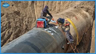
to ensure that the welds are strong and durable following a detailed design plan building a boat without a detailed design plan can lead to errors and inconsistencies that can compromise the safety and performance of the boat be sure to create a detailed design plan that takes into account all the necessary components, materials and specifications of the boat, choose the correct thickness for each component, the thickness of the aluminum used for each component of the boat, such as the transom The undersides, deck and console will depend on the intended use of the boat and the expected conditions it will face.The shorter it is, choose the correct thickness for each component to ensure the boat is strong and durable. Consider weight distribution. Proper weight distribution is important for the safety and performance of the boat. Be sure to consider the weight of the engine, fuel tanks, batteries and other components when designing and building the boat. Test the boat before using it once it is ready. finished, be sure to test it thoroughly before taking it out to sea. water, this will help identify any issues that need to be addressed before the boat is put into regular use. Once all the components of the boat have been manufactured and welded, the boat can be painted or coated with a protective finish to ensure that it will remain in good condition for years, finally the boat is equipped with all the necessary accessories such as navigation lights in the center console with self-bailing and a 50 horsepower Honda engine that can propel the boat to a maximum speed of 30 knots. an onshore facility used to facilitate the continuous laying of pipelines for offshore oil and gas production.
The installation allows for single or double joints of 40 or 80 feet of 4- to 18-inch diameter steel pipe to be welded into predetermined lengths for coiling in an actual run. ship the tracks Narrow gap Mig M technology offers special economic efficiency for welding thick-walled components compared to conventional weld bead preparation the volume of the weld bead can be reduced by approximately 60% narrow gap sheet rectangular with a length of up to 400 MM, guiding the wire electrode, shielding gas and cooling water, welding beads with the typical constant bead structure meet the highest quality demands in the welding process in tandem.
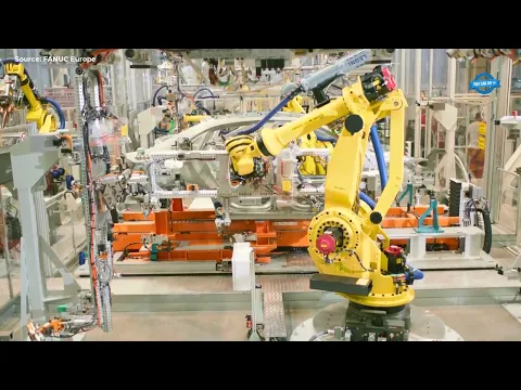
The two electric arcs burn in a common melting bath. Tandem welding is characterized by two electrically separate processes that combine perfectly with each other. This possibility opens up a multitude of combinations. The front wire ensures safe penetration. The back wire quickly fills large joints with filler material. The high deposition rate results in speed. of welding and in filling volume therefore tandem welding is suitable for thin welds and for thick plates Quality W Point number one point number two Audi Hungary is one of the companies with the highest turnover and export in Hungary and produced 2 million engines and 135,000 cars in 2014 with the assistance of fanic industrial
robot
s in its production facilities.Fanic
robot
s are typically used to improve productivity, product quality, cycle times and overall efficiency of a manufacturing process, there are many different applications that fanic robots can be used for in numerous industries, one of the popular applications is welding. Fanic robots are capable of automating arc andlaser
welding, among many other welding processes. processes Fanic arc and spot welding robots are frequently used in the automotive oil and gas sector and fanic welding robots in the aerospace industries produce durable, high-quality welds that are crucial for items manufactured in these industries. The fanic arcmate 120 IC is a popular fanic robot for linear welding automation. lfw friction welding is an established niche technology applied byleading global manufacturers of gas turbine aircraft engines to manufacture vane disc assemblies.The main challenges are associated with the surface area that can be welded due to the high forces required and the control of welding parameters to ensure. precision of the finished part Steel tubes using the submerged arc welding process are manufactured by Hall Longmore with a diameter ranging from 660mm to 2540mm. Steel tubes are manufactured from circularly bent steel plates or can be produced continuously from a coil. of steel strip bent in a spiral and butt welded along the spiral seam. The joints between the coil ends of spiral welded tubes are known as scalps and welds. Butt welded tubes are made of laminated strips with a longitudinal oven seam butt welded using a continuous process.
Point number two A hot spinning machine uses the hot spinning process to shape metal components, first a piece of metal is placed on a lathe, then a blowtorch is used to heat the metal to a high temperature as it The metal turns on the lathe, a tool presses against the heated metal. surface causing it to distort and take the desired shape this process is particularly effective in shaping metals such as aluminum, steel and copper into intricate and precise shapes in the bottom closing operation hot spinning machine is used to shape the lower part of the metal component while in the neck forming operation, it is used to shape the neck or the upper section.
These operations allow the creation of various parts and components used in industries such as automotive, aerospace and manufacturing, where precision and strength are paramount in pipe welding, particularly in the United States. Association Pipeline Local 798 is not just a job, it's a way of life. The document paints a vivid picture of the dedication, pride and skill embodied by those who work in this elite profession. From the beginning, it is clear that pipe
s are a breed apart. Described as the elite among quality workers with a tradition that extends back to monumental projects like the Big Inch and Alaska Pipeline, their work is not limited to comfortable environments, they face extreme climates and terrain, from scorching heat to freezing cold.
welder
s are a breed apart. Described as the elite among quality workers with a tradition that extends back to monumental projects like the Big Inch and Alaska Pipeline, their work is not limited to comfortable environments, they face extreme climates and terrain, from scorching heat to freezing cold.It's bone-numbing, from blizzards to high winds, but regardless of the conditions, they never compromise the quality and craftsmanship of their work. Pipe welding is not for everyone, but for those who choose this career it is a source of pride and satisfaction. It is hard work but it is honest work and there is deep satisfaction in knowing that you have earned your pay through your work. Work is a career passed down through families and local unions with training often taking place in the I work in the field or in Elite welding schools like the one in Tulsa.
What sets pipe welders apart is not just their skill with a torch or their ability to endure. difficult conditions is their unwavering dedication to their craft, they take pride in their workmanship knowing that every weld they perform contributes to the reliability and safety of the pipelines that transport oil and gas across the continent, plus there is a sense of mission among pipeline welders who recognize the importance of their work in ensuring North America's energy independence with a 100-year supply of natural gas available the need for pipelines to transport this valuable resource is greater than ever and are the pipeline welders of the 798 local who are in a unique position to satisfy this need in the end being a pipe welder is not just about the salary or prestige, it is about something deeper, something that swells in your chest and fills your entire soul, it is about of knowing that you are one of the best parts of a select group of trained professionals who get the job done right every time it's about being tough, determined, hardworking, skilled and brave the qualities that define a 798 pipeline the hbam production process built It begins with the dimensional inspection where every aspect of the raw materials is analyzed to meet the specified requirements.
This inspection ensures that the beams are manufactured to precise measurements, crucial for their intended use in construction projects. After the dimension inspection, they are The plate cutting process is carried out, each plate is measured and assigned a unique part number for traceability purposes. This step ensures that the materials are prepared accurately. For the assembly process that follows during assembly, the individual components are joined together to form the H-beam structure. This assembly process requires precision and attention to detail to ensure that the final product meets the required specifications. Submerged arc welding is used to join the components.
Parameters such as current and voltage are set according to the specifications of the approved welding procedure to achieve strong, long-lasting welds. Once the welding process is complete, the beams undergo a straightening process to correct any distortion of the flanges. This mechanical correction ensures that the beams are perfectly aligned and ready for the next stage of production dimensioning. Inspection continues throughout the production process with visual ultrasonic magnetic particle and die penetrating testing methods employed to detect any defects or Irregularity After the installation process is completed by qualified installers and welders, the beams undergo a thorough cleaning process.
It is removed using an automatic shot blasting machine, leaving the surface clean and ready for further treatment. Surface roughness inspection ensures that the surface meets the required standards before proceeding with the painting process. Coating thickness inspection is carried out to verify that the paint coating meets the specified thickness requirements. Once all quality checks are completed, the finished products are ready to be delivered to customers. Large robotic welding revolutionizes the welding process for excavator buckets. Traditionally a labor-intensive task with its streamlined approach. The complexities of robotic welding are simplified into three simple steps. The first step involves selecting the weld and defining the welding parameters, then in step two, the part is scanned.
This step uses advanced technology to precisely map the surface, providing essential data for the welding process. Finally, step three executes the welding itself with the ab robotic system. This phase is perfectly integrated and automated. minimizing errors and maximizing productivity Traditionally robotic welding for excavator buckets posed significant challenges, the uniqueness of each bucket required extensive programming and the complexities of synchronizing the robot and positioner added additional complications, plus the deviations that occurred after bending metal added another layer of difficulty, however, Abe's innovative approach transforms this arduous task into a simple and efficient process by eliminating the need for manual programming, the system dramatically reduces setup time and increases overall efficiency with a Large robotic welding for excavator buckets becomes affordable and hassle-free, allowing manufacturers to improve productivity and quality without compromising complexity.
Structural steel
fabrication
is a multifaceted process encompassing several complex stages that employ specialized equipment and highly skilled personnel to transform raw materials into meticulously crafted structural components essential for various construction projects. At Steel Fat, a renowned structural steel manufacturer, the manufacturing process is meticulously monitored to ensure unwavering quality. Quality and precision standards are maintained from the beginning with the receipt of raw materials. Steel shipments arrive at the facility aboard semi-trailers where they are carefully unloaded and strategically placed within the yard beforefabrication
begins. A meticulous inspection of the steel is performed to determine. Complying with strict quality standards, once the material is approved, it proceeds to the Forms Department.The center of advanced CNC computer numerical control machinery. Here a spectrum of sophisticated equipment is deployed to execute precise cutting, drilling, bending, shearing and burning operations to exacting specifications. The state-of-the-art facility features innovative machinery capable of processing up to 2,000 tonnes of material per week for plate manufacturing. The use of cutting-edge plasma and oxyfuel cutting machines facilitates the precise shaping of complex geometries and the drilling of holes with maximum precision. Additionally, simpler shapes are cut using wide shears and subsequently bent using press brakes to produce a variety of diverse components. The manufacturing of beans, columns, channels, pipes and tubes is organized within dedicated sections of the facility that house beam lines packed with an arsenal of saws, drills, copings. essential auxiliary machines and equipment for handling various materials, each individual part undergoes meticulous scrutiny to ensure compliance with dimensional tolerances and rigorous quality criteria.
The assembly and manufacturing phases are entrusted to a deep team tasked with transposing complex dimensional data from drawings to physical steel components. Heavy manufacturing takes place within specialized workshops equipped to accommodate assemblies weighing up to 120,000 lb. Robot-controlled submerged arc welding machines are used to execute precise and efficient welds that ensure structural integrity. In addition to structural steel, the facility specializes in the manufacturing of various steel products, including stairs. handrails and stairs, these custom-designed sets are crafted from a variety of materials, including stainless steel, brass and aluminum, to suit various project requirements. Compliance with strict quality control protocols is paramount throughout the manufacturing process.
The team of certified welding inspectors meticulously examines all welds with ultrasonics. and magnetic particle inspections performed as necessary to detect any imperfections. Coatings play a critical role in protecting manufactured steel against corrosion and environmental degradation. The coatings department is equipped with state-of-the-art technology to apply a wide range of coating systems ranging from standard shop paint to intricate zinc-based ones. Coatings Once manufacturing is complete, the finished material undergoes meticulous preparation for shipment. Barcode systems are used to meticulously track production and generate accurate shipping tickets, ensuring smooth logistics operations. Tablets allow manufacturing. Real-time staff access to drawings and revisions, minimizing errors and downtime.
The edge gluing machine. Designed to manufacture covers for sheets up to 3.75 mm thick, it is versatile and robust industrial equipment. Its main components and capabilities can be described as follows. The machine is equipped with a 2 horsepower motor along with a reducer. This combination provides the power needed to drive the edge banding process. The motor is connected to the machine mechanisms through a straight chain connection ensuring reliable and precise operation. This edge banding machine is suitable for processing sheet metal. stainless steel and carbon steel and can work efficiently with sheets up to 3.25mm thick for stainless steel and up to 3.75mm thick for carbon steel, built-in sheets accommodate materials ranging from 5mm to 25mm. mm thick, which further improves its versatility.
The machine axles are designed with gear drive and heavy-duty bearings to withstand mechanical stresses. During operation, a set of pulleys made of heat-treated tool steel ensure smooth and precise movement of the blade during the edge-gluing process. The machine features an adjustable support arm made of durable tube material that allows customization to fit specific workpiece guides with adjustable settings. a choice of nylon or steel spools Provide support to the sheet being worked to ensure stability and precision. The machine is equipped with an electrical control system that incorporates safety relays, which guarantees safetyof the operator and helps prevent accidents during operation.
The exterior of the machine is covered with synthetic material. enamel paint that provides protection against corrosion and improves its aesthetic appeal. This edgebander offers flexibility in the parts it can process. It can work with a minimum part radius of 150 mm and a maximum part radius of 3,000 mm. It is suitable for handling conical pieces. and flat parts with edge angles up to 100°. Head forming is a critical process in the manufacturing of pressure vessels such as boilers and tanks. These vessel heads, usually made of materials such as steel or aluminum, play a vital role in safely containing and maintaining internal pressure.
The head forming process involves shaping flat plates into curved or domed configurations, ensuring they meet specific design requirements and safety standards. Common methods include cold forming, hot forming and spinning. Cold forming uses hydraulic or mechanical presses to bend the material, while hot forming involves heating the material to make it more flexible; spinning uses a ribbon-like machine to rotate and shape the material into the desired contour. Cutting The first step in the manufacturing process is cutting, in this step the raw material in the form of steel bars is cut into specific lengths required for production. of combined wrenches this process is carried out with the help of a shearing shot blasting machine the next step is shot blasting in this step the cut steel bars are cleaned and prepared for forging by blasting them with abrasive materials such as steel shot or sand to forging The third step is forging.
In this step, the prepared steel bars are heated in a furnace to a specific temperature and then shaped into the desired shape using a forging press. The forging process compresses the steel, making it stronger and more durable. The steel bars are heated to 1,250° centigrade to prepare them for the hot rolling process. In this step, the heated key blanks are fed through a series of rollers which reduce their thickness to the required dimensions. The hot rolling process involves feeding the heated metal strip or sheet. a set of rollers that apply pressure to reduce its thickness the temperature and pressure of the rollers are carefully controlled to ensure that the metal is not overworked or damaged during the process the hot rolling process can be repeated several times to achieve thickness and desired mechanical properties to cool, the forged key blanks are cooled to room temperature to avoid any deformation or distortion caused by the high temperatures used in the previous steps.
In this step, the cooled key blanks are cut into individual keys with the help of a sandblast cutting press. After cutting, the individual keys are cleaned and prepared for further sandblasting. This step removes any rust, dirt or other impurities present on the keys. Polishing is a critical process to achieve the precise dimensions and smooth surface finish required for keys after keys. They are cleaned and sent through a grinding machine that removes rough edges and surfaces. The grinding process is automated and controlled by computer programs to ensure consistency in the finished product. In this step, the sandblasted keys are placed in a drum. with abrasive media such as ceramic shavings or falling steel pins Smoothes and polishes the surface of the keys removing sharp edges or burrs and improving their appearance Coining The next step is to coin In this step the combination keys are pressed into a die to create the final shape and surface texture Coining further improves the strength and durability of keys by increasing their density.
Drilling In this step, combination wrenches are drilled with appropriately sized holes to accommodate bolts and nuts of various sizes. After drilling, combination wrenches are drilled to create the characteristic square openings. Required to set bolts and nuts by turning the combination. The keys are put back into a socket to remove any remaining burrs or rough edges caused by the broaching process, after that the keys are sent to a heat treatment process . Heat treatment involves subjecting wrenches to extreme temperatures to alter their physical and mechanical properties in the case of beta tool combination wrenches, the heat treatment process involves hardening and tempering the wrenches to increase their durability and strength.
The heat treatment process begins by heating the keys to a temperature of around 860°C, at which point the steel undergoes a transformation called idiz the. The keys are then cooled in an oil or water bath to rapidly cool them and transform the tinite into martensite, a hard crystalline structure. After cooling, the keys are quenched by heating them to a temperature of around 560°C. The tempering process allows the Martin site to be transformed into a tempered Mart site that is stronger and more ductile than the untempered Martin site. Polishing In this step, the combination wrenches are polished to give them a final shiny appearance.
Nickel-chrome plated. The last step in the manufacturing process is nickel-chrome plating. Combination wrenches are electroplated with a layer of nickel and then a layer of chrome to provide a durable, corrosion-resistant surface finish. Verification and inspection play a crucial role in the beta tool combination wrench manufacturing process. Quality control measures are taken at every step of the process. To ensure that the final product meets the required specifications and standards, various inspection and testing techniques are employed to detect any defects, inconsistencies or failures in raw material components and finished products. These techniques may include visual inspection, dimensional inspection, non-destructive testing, NDT, and functional testing.
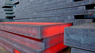
Pouring a cast piece of iron at the Pilson Steel Foundry is a fascinating and complex process that displays the pinnacle of precision and teamwork in the world of metalworking. The foundry, with its state-of-the-art facilities and highly skilled team, orchestrates this procedure with remarkable delicacy. The process begins with the preparation of the iron which is heated to its molten state in a huge furnace. The fiery glow of the furnace illuminates the foundry like A miniature sun is both impressive and a testament to the intense heat required by iron. reaches its liquid state it undergoes careful quality controls to ensure it meets the demanding specifications required for casting the pilson steel team is well coordinated and dressed in protective equipment takes its positions around the pouring area the mold is placed Intricately designed and meticulously crafted casting in place with remarkable precision When the molten iron reaches the ideal temperature and quality, it is time for the impressive moment of pouring.
The crane operated with utmost precision lifts the crucible containing the molten iron and slowly places it on casting mold as the crucible tilts a A burning stream of liquid metal cascades into the mold. The sight and sound are impressive, resembling a volcanic eruption on a smaller scale. The entire process is a harmonious dance of man and machine where every movement is perfectly synchronized and synchronized. The experience of the Pilson Steel team. Ensures that the iron flows smoothly into the mold filling every intricate detail. Any errors or deviations could result in a faulty casting making the teamwork and precision involved even more crucial.
The production of osca machinists hammers is a good example of engineering. Precision and Craftsmanship The manufacturing process begins with the selection of high-quality materials, including C45 electroinductively hardened steel for the head and a patented three-component handle. Once the steel has been electroinductively hardened, it is forged into a hammer head shape. Forging involves heating steel to a high temperature and then shaping it using a series of dies and hammers, this process helps create a strong and uniform grain structure in the steel which further improves its durability and wear resistance. After the Hammerhead has been forged, it undergoes a series of grinding and smoothing processes to create The Hammerhead is then lacquered to obtain a smooth and uniform surface to protect it from rust and corrosion.
The striking faces and blunt edges of the Hammerhead are polished to a mirror-like finish using a series of polishing wheels, creating a flat, smooth surface that is ideal for striking metal surfaces without leaving marks or dents in the production of osca machinists hammers Robots are used in the manufacturing process to ensure precision and consistency The robots are programmed to perform a series of tasks such as forging, grinding, smoothing and polishing with a high degree of precision and efficiency, this helps ensure that each hammer produced is of the same high quality and meets the strict standards set by the company.
The patented three-component handle is made of a nylon outer layer, a non-slip rubber grip and an aluminum alloy core. The design helps reduce vibration and makes it easier to grip and hold the hammer during use. The handle is also designed to be comfortable to hold, reducing the risk of hand fatigue during prolonged use. The head of the hammer is mechanically attached to the handle using a steel rod. wedge and red epoxy resin, this ensures that the head is firmly attached to the handle, reducing the risk of the head coming loose during use. Once the hammers are manufactured, they undergo rigorous quality control procedures to ensure they meet the high standards set by the company, this includes testing the hammers for durability, safety and reliability. collaborative robots.
Cobots have significantly impacted the welding industry by automating processes that were previously labor-intensive and potentially dangerous when used to automate the welding process. Cobots provide several innovative features and functionalities. Cobots with sensor technology. They are equipped with sensors that allow them to detect the position and orientation of workpieces accurately in welding applications, these sensors allow cobots to precisely locate the welding scene and adjust their movements accordingly. Integration of welding tools. Cobots can be equipped with welding tools such as Mig metal. Tungsten inert gas TIG or inert gas welding torches that are specifically designed for robotic welding applications.
These tools are mounted on the cobot end effector and precisely controlled to perform the welding process. Real-time monitoring cobots use vision systems and other sensing technologies to monitor welding. real-time process can detect variations in the welding environment, such as changes in material thickness or joint misalignment, and make adjustments to ensure consistent weld quality. Collaborative operation, while cobots are capable of operating autonomously. They can also work in collaboration with human welders. Tasks such as spot welding or seam tracking while human operators focus on more specialized aspects of the welding process, such as joint preparation or quality inspection.
Security features. Safety is paramount in welding applications, especially when humans work alongside robots. Cobots incorporate safety features such as collision detection. Speed and force limitation and safety rated software to ensure the well-being of human operators. The Y a Arc World dual welding robot operates on the principle of coordinated movement between two robotic arms, amplifying both speed and precision in welding tasks. These robotic welding systems are pre-designed and pre-assembled, arriving ready to weld, thus offering a flexible and cost-effective solution for integrating robotics into welding processes. Arc World work cells can be configured with multiple heavy-duty positioning robots or servo-controlled external axes to facilitate synchronized motion, allowing them to handle large, heavy-duty part welding and deposition efficiently with the ability to handle parts up to 5m in size and payloads of up to 6300kg, Arc World work cells are particularly suitable for labour-intensive tasks involving substantial components.
One of the key features of Arc World is its ease. of integration despite its size and power,These work cells are designed for easy installation and relocation and arrive pre-assembled on a common base. Additionally, they are modular and scalable, allowing easy expansion of productivity without requiring additional space from single stations to dual robot configurations. World System adapts perfectly to changing production demands, ensuring greater efficiency in welding operations. The integration of robotic welding technology into the production of aluminum tanks represents a fundamental advance in manufacturing efficiency and precision. Traditionally semi-automated welding processes required manual intervention, limiting productivity and consistency, however, the adoption of robotic welding systems heralds a transformative change that allows companies to meet changing market demands with unparalleled efficiency.
Previously, aluminum tank production relied on semi-automated manual stapling operations that, while functional, lack the precision and speed necessary to remain competitive. Recognize the imperative for improvement that companies have. They turned to robotic welding systems to revolutionize their manufacturing processes. These robotic systems typically feature multiple workstations that allow for continuous operation without downtime while the robot performs welding tasks at one station. Staff can load and unload materials at another, ensuring optimal utilization of available production time despite initial difficulties. investment required for implementation the benefits of robotic welding technology are multiple companies experience significant cost savings with machine hours per seam reduced by up to 50% this increase in productivity and flexibility not only improves profitability but also allows better adaptation to fluctuating production demands in addition to robot welding systems ensure consistent quality and precision, leading to a reduction in defects and an overall improvement in product standards.
The ability of robots to operate continuously without fatigue or interruptions further optimizes production, extending working hours. Beyond the length of traditional shifts, it is important to highlight that the introduction of robotic welding does not imply the loss of employment, but rather redefines the roles of personnel by focusing on tasks such as assembly and material handling, uniformity and efficiency. of the robot's operations positively impact subsequent manufacturing stages, resulting in cascading benefits throughout the entire production process. Early tests and acceptance tests have shown promising results with significant results. The reductions in cycle time observed, this rapid change underlines the potential for a rapid return on investment, positioning companies at the forefront of innovation in aluminum tank manufacturing.
The IGM RTE 400 series of robots represents the culmination of more than 40 years of experience in welding robot development and production plant planning, this series offers a wide range of system modules, the main module being the RTE 400 , recognized for its exceptional performance and versatility, at the core of the IGM robot's capabilities are its excellent programming techniques, facilitated by both the k6 programming pendant system and an offline teaching system, this dual programming approach provides users flexibility and efficiency in programming, allowing seamless integration into various manufacturing environments. The IGM robot design prioritizes optimal performance with a large work area and perfect welding access to seam positions.
This is achieved through optimal shaft geometry and mounting of the welding torch on the wrist shaft, which is implemented as a hollow shaft, in addition, all cables are carefully routed within the robot arms using hollow shafts, ensuring a neat setup and minimizing interference. Modularity is a key aspect of the RTE 400 system with extremely thin robotic arms that are optimized for weight and rigidity. Different arm lengths are available for 2nd and 4th axes, allowing users to select the appropriate range of motion for their specific applications, improving versatility. High-performance components are integral to the operation of IGM robots, including highly dynamic maintenance-free AC servo motors and cast aluminum rigid joint constructions, these components ensure high rotational speed, rapid acceleration in all axes and Minimum maintenance requirements that contribute to overall efficiency and reliability.
Specialized for arc welding, IGM robots feature a unique design where all welding media is directed through the main axis and then through the hollow shaft to the wrist axis, this design allows the welding torch to complete two full turns, improving accessibility to tight workpieces and circular seams, thus ensuring precise and efficient welding operations. The axis of the IGM robot. The layout and integration are meticulously designed to optimize performance and functionality. Shaft one serves not only as the drive shaft but also houses welding media such as cooling hoses, gas hoses, cable conduit hoses, water cooled cables for welding, power connection and control cables for wire feed, Additionally, the wire feed is integrated into The axis one is protected from environmental influences with a cover that maintains a slim profile for the robot and welding equipment.
Versatility is a hallmark of the IGM robot series with options ranging from six to eight AIS welding robots to suit various welding applications, as well as multi-purpose IGM robots. They are capable of welding, cutting, chamfering and other tasks, offering true multitasking capability with the ability to swap tools as needed in various applications such as pick-and-place welding assembly and smart manufacturing processes. IGM robots demonstrate their versatility and efficiency, making them an indispensable asset in modern industry. manufacturing environments with its advanced technology Precision engineering and modular design IGM robots redefine standards for welding and manufacturing automation in LNS North America the production process for custom conveyors Manufacturing is a perfect combination of cutting-edge technology, specialized craftsmanship and Meticulous attention to detail.
The process begins with cutting raw materials using a state-of-the-art AR 6K fiber optic
laser
. The next step involves the use of metal press brakes that allow for precise bending and bending. Shaping of components to meet exact design specifications. After the bending process, the components are transferred to ergonomic soldering stations where expert welders like Ethan Cooper meticulously join the parts. Their experience ensures that each weld is strong, durable and seamlessly integrated into the placement. Basis for a reliable conveyor system After welding, the components undergo a metal finish polishing to smooth out rough edges and imperfections, ensuring a flawless finish.This step not only improves the aesthetics of the conveyors but also improves their functionality and longevity once the components are properly finished. continue with mechanical assembly, where they are expertly assembled onto the final conveyor system. This stage requires careful attention to detail and precision to ensure that all components fit together perfectly and function as intended. Finally, the assembled conveyors are moved to the paint booth where they receive a durable finish. and a visually appealing finish, this finishing touch not only enhances the appearance of the product but also provides protection against corrosion and wear, ensuring long-term performance and reliability throughout the production process, collaborative communication and The commitment to excellence is paramount from the cutting of raw materials to the end.
The assembly and finishing of each step is executed with precision and care, resulting in custom conveyor systems that meet the highest standards of quality and performance. The video shows the piston manufacturing process by Ms Motor Service international gmbh. The raw materials used in the process are mainly aluminum alloys. The piston mold is made of sand that is packed around a pattern of the piston. Molten aluminum is then poured into the mold and allowed to cool and solidify. Machining The piston is then machined to achieve the desired dimensions and surface finish. This involves cutting and shaping the Piston using specialized tools such as lathes, drills and grinders, 100% accurate x-ray inspection is an important quality control step used in piston manufacturing to ensure that the piston channels piston cooling are free of defects and meet the specifications required on production lines. flexible that allows the manufacture of pistons with a diameter of 65 to 135 mm surface treatment the piston undergoes several surface treatments to improve its durability and resistance to wear the surface treatment process includes the use of Nano, a coating technology that improves quality of the surface and reduces friction, this surface treatment ensures that the piston is more durable and has a longer service life.
QA. Pistons undergo rigorous quality control measures throughout the manufacturing process, including dimensional checks, hardness testing and visual inspections. Steel drums, also known as steel barrels or steel containers. They are widely used for the storage and transportation of various materials, such as chemicals, foods, and hazardous substances. These tough, reliable containers are essential in industries around the world. The manufacturing process of a steel drum involves several complex steps to ensure its durability and functionality. The steel sheets are cut into the desired size and shape. The dimensions of the steel sheet will determine the final size and capacity of the steel.
Edge bending After cutting, the edges of the two ends of the steel sheet are folded to create a smooth, rounded edge. Rolling into a cylinder, the steel sheet is then rolled into a cylinder shape forming the body of the steel drop by pressing the edges to secure the seam and create a closed cylinder. The edges of the steel plate are pressed together using specialized machinery. This process results in a hermetically sealed joint that prevents any Le or Spill insertion of the pin after pressing a pin is inserted through the seam to hold it firmly in place the pin ensures that the seam remains intact during use and transportation of the Drum This step adds an extra layer of safety to the construction of the drum Creating ribs to reinforce the structure and add strength to the drum Ribs are created on the outer surface of the cylinder These ribs provide rigidity and help prevent the drum from warping or collapsing Under the weight of its contents the ribs are generally spaced evenly around the circumference of the drum.
Pressing the bottom plate The next step is to press and seal the bottom plate into the body of the drum. This plate is usually made from the same type of steel as the body and is fitted and welded into place. The pressing process ensures a tight seal making the drum completely airtight and safe. Installing the drum closure depending on the intended use of the steel drum. A locking mechanism is installed on the top of the drum. Common closure types include a removable cap. Caps or a locking ring. These closures provide access. to the contents of the drums while maintaining their quality control integrity throughout the manufacturing process.
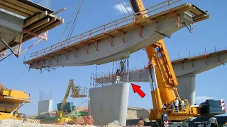
Quality control measures are implemented to ensure that each steel drum meets the required specifications and standards. This includes checking for defects on site, ensuring the drum is leak-proof, and checking the structure. Rib and bottom plate integrity testing of steel Dr drums. They can undergo various tests, such as pressure tests, to check their strength and leak resistance. This testing helps ensure the reliability and safety of the drums. The integration of welding robots into the bridge manufacturing process marks a significant advance. in the field revolutionizing traditional manufacturing methods historically manual welding has been the norm for bridge structures due to its complex and often C nature;
However, the arrival of technologySophisticated robotics have reshaped this landscape offering a host of benefits in terms of efficiency, precision and productivity, one of the main challenges in adopting welding robots for bridge manufacturing lies in the variability of bridge parts. Each component tends to be unique, which presents challenges for conventional robotic programming; However, advances in computer vision and algorithms have allowed robots to adapt to this variability without the need for extensive programming. This flexibility allows manufacturers to effectively use robots for custom projects and even component parts that overcome previous limitations. A case study from a bridge manufacturing company highlights the transformative impact of robotic welding.
Initially, the company struggled with limited capabilities of the robots and programming difficulties that restricted them to simple parts. However, in welding, with the implementation of Abaj robotic cells equipped with machine vision technology, the company witnessed a notable transformation in its production capabilities. The use of two robots equipped with artificial vision sensors along with advanced software allows for seamless integration of the robots into the manufacturing process that these robots operate. Tracked within a wide work area that accommodates large Bridge components with ease, the Machine Vision system scans parts detecting any deviations from the 3D model and adjusts accordingly, ensuring precise and accurate welding, efficiency gains achieved by through robotic welding are substantial, the company reports a three-fold reduction in costs and a five-fold increase in throughput, plus savings in grinding wire and welding gas costs, plus the system's ability to Identifying assembly defects before welding avoids costly rework and ensures product quality. materials to which each plate is subjected Dimensional inspection to verify compliance with the specified dimensions.
Following material inspection, the plate cutting process occurs during which precise measurements are taken and part numbers are recorded to maintain traceability throughout production. Bevels are then prepared on the edges of the plates to facilitate proper fit during welding, subsequently diaphragms are carefully placed into the box column structure to provide additional support and reinforcement while backer strips are inserted into the joints. to aid weld penetration. The next step is to assemble the three-sided box structure, preparing it for welding processes. Hand welding secures the diaphragms in place ensuring structural stability. Ultrasonic tests are then performed to inspect the quality of the diaphragm welds, identifying any defects or discontinuities.
Cover plates are then placed on the box column structure to enclose the assembly. Welding processes are critical steps of the box column. GMaw production gas metal arc welding is used for root pass welding, providing strong and reliable fusion submerged arc welding. The saw continues with current and voltage settings adjusted according to the specifications of the approved welding procedure to ensure consistent, high-quality welds, and holes are drilled in preparation for electroslag welding. esw allows vertical welding of diaphragms. esw is then employed for this purpose, ensuring an efficient and robust fusion between the diaphragms and the box column structure.
Quality inspection is paramount throughout the production process. Visual tests. Ultrasonic testing and dimensional checks are performed to ensure that all welds meet requirements. standards and specifications Face milling is performed to achieve smooth, uniform surfaces, followed by a final dimensional inspection to verify compliance with specified tolerances. The fitting process ensures proper alignment and assembly of components before welding. Qualified installers meticulously assemble the various parts of the box-shaped column structure, including plates, diaphragms and cover plates according to precise specifications and assembly drawings, once the assembly process is completed, qualified welders will They are responsible for carrying out the welding process.
Surface preparation involves removing rust using an automatic shot blasting machine. Prepare the surface for painting. adhesion and paint protection, after which the box column undergoes the painting process for corrosion protection and aesthetic improvement. A coating thickness inspection is performed to verify compliance with specifications. Upon successful completion of all quality checks, the finished box column is prepared for delivery to the customer, ensuring that it meets the highest standards of quality and reliability. Sand casting is a versatile and widely used manufacturing process with a rich history in the production of metal parts. The process begins with sand mold design, a crucial step to ensure accuracy and quality using patterns made from wood.
Metal or plastic sand is mixed with binders and hardeners in high-speed mixers. The resulting mixture is poured into molds containing the patterns. In just a few minutes, the sand solidifies allowing the mold to separate from the pattern. Skilled teams can also create cores to establish internal passages. Within the foundry, once these stages are completed, the moles are sealed and prepared for the essential metal pouring phase. Sustainability is a fundamental principle in sand casting. At Precision Aluminum Casting and Engineering, the company employs a computerized recovery system to minimize sand waste by recycling it in the production cycle, and its commitment to environmental responsibility is exemplified by the adoption of a low-odor urethane system to sand molds, reducing environmental impact while maintaining high quality standards.
Sand casting remains a vital and environmentally friendly manufacturing technique in various machining industries. edl has invested significantly in expanding. and enhancing their SE n c turning and milling capabilities, they machine castings from bar and billet materials using state-of-the-art machinery that ensures the highest quality components. They also offer conventional machining services, including jig grinding and boring. Universal milling and turning. Its foundry services cover. Aluminum, brass and bronze with three main casting methods: sand casting, gravity die casting and investment casting. They work with various grades of non-feris alloys, including aerospace-specific aluminum alloys, and provide in-house design capabilities for investment castings and die castings in the manufacturing process.
For hex head anchor bolt it involves several steps including cutting, chamfering, tapping, hot-dip galvanizing and finishing. The following is a step-by-step guide to the manufacturing process. The cut steel round bar has a diameter of one and a/4 inches by 48 inches long. galvanized, is cut to the required length using a cutting house. The hex head is hot forged into one end of the steel rod using an induction heating coil that heats the end of the rod to about 2000°F and then the national upsetting is used. To forge the heated end of the rod into a hexagonal shaped head, grip blocks hold the round bar securely in place while a plunger or die compresses the heated end of the rod and reshapes the rod configuration. hexagonal head, then the manufacturer's logo and grade symbol are displayed. stamped into head as needed chamfered high speed cutting blades apply a chamfer to the ends of the bolts before threading this chamfered end will help facilitate nut assembly once the bolts have been tapped and tapped galvanized are used Landis threaders to cut 8 inches of thread on the end of these anchor bolts.
The rotating heads contain chasers that cut the steel from the round bar to produce the threads. A constant flow of cutting oil is applied to reduce friction and prevent overheating. Threading operators measure threads to ensure compliance with dimensional tolerances dip galvanizing removes cutting oil and other organic materials that build up during manufacturingDuring the welding process, bolts are rinsed and immersed in sulfuric acid, which removes scale from the bolts and etchs the surface of the steel. The bolts are rinsed again and then dipped in flux, which is a chemical that helps bond the zinc to the steel.
After stripping, the bolts are placed on racks and lowered into a tank 12T long by 4T wide. per 7t depth of cast 840 zinc. The bolts remain in the zinc for between 2 and 4 minutes when removed from the zinc in which they are turned. a high-speed centrifuge to remove excess zinc from the threads and finish the bolts are cooled in tempering tanks so they can be inspected and packaged as soon as they are removed from the galvanizing tank. Estwing is a family business that manufactures high quality handcrafted products. tools in the United States for over 90 years. The company's manufacturing facility is located in Rockford, Illinois, and the company prides itself on designing and producing the most durable, eye-catching, comfortable and attractive tools in the world.
In this video we will focus on the manufacturing process of Swing hand tools. The first step in the manufacturing process is forging the swing hand tools. They are completely forged, meaning they are formed from a single piece of steel. The forging process involves heating the steel to a high temperature and then hammering it into the desired shape. This process gives swing hand tools their strength and durability. After the forging process the hand tools are heat treated to harden the steel. This step ensures that the tools can withstand the wear and tear of heavy use. After the heat treatment process, the forged steel hand tools are ground to create a smooth, uniform surface.
Surface grinding is a process of removing small amounts of material from the tool surface using abrasive wheels or belts. This process helps refine the shape of the tool and create the desired surface finish. Once the grinding process is complete, the tools are polished to further refine the surface and create a smooth finish. Next, the hand tools are equipped with swing's patented shock reduction grip. This grip provides customers with the best grip available to reduce vibrations caused by impact and offers the ultimate in comfort and durability. Vinyl and nylon grip tools are now made with this new material.
Finally, hand tools are tested for hardness and strength to ensure they meet Swing's high quality standards. Each tool is carefully inspected to ensure it meets the company's exacting specifications. The three-reel variable. DVI's axle plate rolling machine known as MAV is a robust and versatile piece of equipment designed for bending thick plates with a thickness of up to 130 mm. This machine works by taking a flat plate and expertly shaping the three rolls into a cylindrical shape. Driven by powerful motors they work together to bend the plate with precision and efficiency. Key features of the math include motorized rollers for precise control.
A sturdy frame that ensures stability during operation and the ability to tilt the rollers for precise cone bending. The machine benefits from mechanical and hydraulic Symmetry which improves bending precision and ensures uniform load distribution across the plate. One of the standout features of the MAV is the patented servotronic copyright system that maintains the parallelism of the rollers throughout the bending process, ensuring a high level of precision in the final result. In addition, the multi-gearbox configuration improves ease of operation and simplifies maintenance procedures. The TS s D600 servo press using Schuler's Servo direct technology is a cutting-edge machine designed for various manufacturing applications ranging from automotive components toappliances such as washing machines and dryers, this 1600.
T servo press offers a substantial increase in part production of up to 50% compared to traditional mechanical presses. Thanks to its innovative features, the press operates without a traditional flywheel or clutch brake combination, making it exceptionally flexible, energy efficient and low maintenance. It is directly driven by high torque. Motors that provide the necessary force for dynamic forming processes. Its highly energy-efficient pendulum stroke operation allows programmable ram strokes without mechanical stroke adjustments, resulting in a higher number of strokes per minute. In addition, the TSD 1600 servo press offers extensive flexibility in production. The press allows free programming. lifting heights and motion sequences resulting in higher production and higher part quality Schuler has also developed specialized software tools such as the smart assist optimizer and the optimizer pro to optimize operations and improve part quality.
One of the key advantages is the tool that reduces configuration and testing times. training periods and maximizing production efficiency, the press can seamlessly integrate downstream processes, such as welding or laser, due to its programmable time, distance and rest time sequences. Provisions Schuler offers a range of servo presses in TI rod design with pressing forces ranging from 8,000 kons to 32,000 kons. Catering to a wide spectrum of manufacturing needs, this is an overview of the tumbler set. The factory in China produces a range of socket sets with various options such as metric or SE sockets made from steel or CRV carton, and includes ratchet wrenches, screwdrivers and more socket sets.
They are a collection of sockets, ratchets and other tools used to tighten or loosen bolts and nuts by applying torque to them. Ferrules come in a variety of sizes and shapes to fit different types of bras to make the task of fastening more convenient. The bushings are often packaged together. in a set along with a screwdriver tool such as a hand wrench or air impact wrench, this collection of tools is called a socket set. Socket sets may vary in the sizes and shapes of sockets they include with each set designed to meet specific fastening needs, plus some socket sets may include other accessories such as extensions or adapters to provide greater versatility in use. .
The versatile and compact 100 vclt 100 laser tube is a cutting-edge laser technology system from mazik that operates on direct diode laser technology, unlike traditional fiber or solid state laser systems, this technology. Offering improved efficiency and reliability, the V CLT 100 is specifically designed to provide a cost-effective solution for processing low-volume bar and tube components with a maximum diameter of 100 mm 4 in round or 3 in square and lengths up to 12 feet with a Optional 24 foot extension. One of the standout features of the vt100 is its compact design that allows it to take up little space, making it an ideal choice for environments with limited space.
In addition to cutting tube, it also has the ability to cut flat sheets up to 20 to 24 inches with a maximum thickness of 1/4 in. This versatile system offers high-end performance while maintaining an attractive price, making it an excellent choice. for various applications in the field of laser cutting. The OEM IND Original Equipment Manufacturer in India. has seen remarkable growth and transformation in recent years, making it a major contributor to the country's manufacturing landscape; The sector spans a wide range of industries including automotive electronics, aerospace and more and has played a pivotal role in boosting India's industrial production and exports in In this section we will provide an overview of the OEM industry in India with specific numbers.
The Indian OEM industry has been on an upward trajectory with impressive figures showing its growth. The OEM industry in India has witnessed substantial growth with revenues increasing steadily over the past few years. has contributed significantly to the country's GDP in 2021. The revenue of the OEM industry was estimated at around 2.67 lakh Indian rupees CR approximately 36 billion US dollars. The OEM industry has been a key contributor to India's exports in FY 2022. 12 billion US dollars, the industry has been a major source of employment directly and indirectly for millions of people in India. It provides employment to engineers, technicians, assemblers and support staff in various sectors. sectors, India's OEM industry has a strong presence in multiple sectors including automotive, consumer electronics, industrial machinery, defense and telecom.
The automotive motif sector in particular has been a major driver of growth, with India being one of the largest automotive OEM centers in the world and a notable player in this industry is essential Auto, a leading OEM in sheet metal components and assemblies metallic. It primarily operates as a top-tier supplier to the automotive OEM and home appliance industry, providing high-quality products and services to renowned customers such as LG Samsung dyin and Yamaha. The company has achieved an impressive annual performance. turnover of 75 CR Indian rupees, which is approximately equivalent to 15.4 million US dollars
If you have any copyright issue, please Contact