BitBastelei #512 - Linearregler vs. Schaltregler
Mar 13, 2024It's time to get crafty and today we're going to deal a little bit with the power supply and at least part of it when we're playing with our Arduinos ESP or other digital2, then the power usually comes from some DC source, which can be the battery , For example. or a USB power supply. In most cases, our own circuit operates at a lower voltage than what we get. A simple USB connection that supplies, for example, 5 volts of ESP or current microcontrollers that need 3.3 volts, so now we have to do it. go and get the voltage Making it smaller There are two big concepts for this: the linear regulator and the switching regulator.

They both have their pros and cons, they both have their uses, and they both end up on the craft table over and over again, and consequently, so should they. be today's topic, let's take a look from the beginning at a comparison that is not correct front and back, but at least roughly explains the principle of where the difference is between the two, we assume that we have a water supply that cannot be set to a constant power level in any meaningful way, but can only be turned on and off if we have a lot of water or no water at all.

More Interesting Facts About,
bitbastelei 512 linearregler vs schaltregler...
Now we can imagine the linear regulator as a small tube that we place. can hold back the stream of water, so less water comes out of our tube than we put in the front of the hose, but hey, you can probably already see the problem, everything else we don't need goes wrong, so. there are a lot of losses, but it still has its advantage because we really only need this tube and somehow we can determine our water here and we don't have to worry about anything else anymore. A switching regulator that has it here is used in a slightly different way. structure, which here is basically like a can and if you put water in there, it's a small spoon, then we get less water than before and this is an advantage over, well, our water is not lost, but the climate is lost. temporarily stored in the can, but now we have to do it.

Well, we can't leave the water running all the time, otherwise our can would overflow and break, but we have to go there and keep the water on. water on water on water and we also have to be a little careful if we have too much water, it overflows again if we have too little water, then the can empties and nothing comes out. The advantage is that we do not lose water, everything comes together at the end of our circuit but we have to make more effort, we have to be aware all the time, so it is much more complex, but let's put it all together.

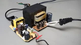
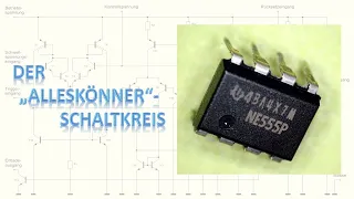
Let's leave these simplifications aside and go back to the R electronics and here we will also start with the classic. In the past, for example, the 7805 was often found in the so-called linear regulator. Today, the 1117 in the 3.3 volt version. This can be found, for example, on many Arduino boards. The motto of such a linear regulator could be described as simply no complexity, as you can see, also what is needed for its operation: just the IC, well, in practice, some capacitors are added and. If it is a model where the voltage is not programmed, you may need a few more resistors.
But in principle, a chip like this can work without a lot of things around it, so you not only have to connect external components and the function is also relatively simple. I know the voltage divider. I hope so. You take two resistors and clamp them one behind the other between the positive and negative poles and now a voltage is applied and then divided between the resistors. Now I have 10 volts from my power supply and then I have two 10 resistors behind them in total, so 10 + 10 is 20 ohms and only then do we get the middle. That means that 10 on the top is still 10 of 20 or shortened one of two and half means half the voltage that we have at the end in the collaboration 10 volts, so theoretically we can also measure 5 volts and yes, pi multiplied by the thumb, 5 volts, a little tolerance from them.
The resistors stop and by the ratio of the resistances we can then also determine the voltage across the medium. Now we had half, that is, 5 volts, if we now swap the resistance in the positive direction, for example with 20 oh, then we have a total of 30 and see below, well, 10 volts divided by. 30 times 10 or a third we arrive at 3.3333 volts, we can also see that, approximately it is there, there is only one small drawback, everything here only works when discharged, that is, discharged, well, it only works as long as there is no charge As long as we do not use actually the 3.3 volts, we can also see here if I get my motor here and connect the adapter to the 3.3 volts, suddenly we no longer have 3.3 volts but a significantly lower voltage.
Well, to put it simply, in many places our load is nothing more than a resistor, another way towards the negative pole or ground, which means that now we have two resistors in parallel and we know that if we connect resistors in parallel then the total resistance decreases and as a result our ratio changes here and yes we have the wrong voltage accordingly. Now, of course, you can start adjusting the resistors to fit again, for example by making the plus direction smaller or the other larger and. then push it back to the 3.3 volts but of course it only works if the load is the same all the time with one more motor it could possibly still work but at the latest if we have some kind of microcontroller that for example does something occasionally sends WLAN or, like here, just lets an LED flash.
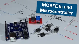
Well, sometimes we need power for the LED, sometimes we don't, which means our load is constantly changing and we would have to adjust. the resistors accordingly all the time, which of course is not that practical. Then we have to find a way for this resistor to automatically change its size so that our target voltage is applied to the output. Yes, the correct component is the old transistor. It is true that nowadays in many cases you only use it to turn things on or off, but a transistor can do more than turn on and off because, well, transistor is the original name for resistor, that is, transmission resistance.
You can make a transistor like this act a little. That is the so-called linear range and that is where it behaves similar to a resistor, only we can change the size electrically, it is still used today for example in amplifiers. for analog stuff like audio or radio we can use that too, we just have to find a reference that somehow means something that gives us the voltage it's supposed to hold. The solution to this may be a special refresh op amp. IC or a simple Zener diode. The latter is basically something similar to a normal diode.
It works the same way forwards, but it works the other way around. A special property is usually that the diodes do not conduct backwards and block the Z diode that can conduct. It only does enough for a certain voltage to be established and if we then use it to power the base of the transistor we have a scooter of 3.3 volts and it stays there even if we change the load. In reality, current linear regulators are. Of course, a little more complex than here, a very simple structure, many of the same, for example, temperature fluctuations because such zi or with the temperature can drop a little, often there is a short circuit protection that automatically turns off if There is a short circuit that automatically shuts off if the thing threatens to overheat, but the basic principle is the same, the thing acts as if it automatically adjusted before the resistance stopped.
A transistor, as already mentioned, is all very simple and therefore easy to install on your own circuits. In many cases you just check that the chip's output voltage and desired current match and yes, and then when you have the right component you just build it in the middle and that's it, if you want. If you want to look a little closer, there are some other values that may be interesting, for example voltage drop, which describes the minimum distance between the output voltage and the input voltage, here the 1 is 7 of the The ESP has for example from 1.1 to 1.3 volts, that is, if we want to have 3.3 volts then we have to have at least 4.6 volts at the input otherwise it will not work correctly.
Another value that may be interesting because it is this. one, I'm trying not to say it now, is the quiescent current and this value describes how much current the circuit requires if we don't have anything connected at the end and yes the AMS 1237 isn't that good either, sometimes it takes 11 milliamps, an example rather negative, if you get something else it can also be done in the microphone amp range and that of course is a problem if you want to build things that run on battery, so linear regulators are great and solved. Well, almost because, as I said, physics should also have a say because of the structure, the current flowing through all the components always has one ampere at the output, so inevitably we have more at the input, but wait a minute, 3, 3 volts with one ampere. at the output it is 3.3 watts 5 volts at the input with an output amperage of 5 watts my calculations say that somehow there is a 1.7 watt difference between them and the law of conservation of energy says no They can magically disappear.
The solution here seems. Losses, a lot of losses because what our transistor does is, well, the difference with the voltage that we have, which it just converts to heat, it's very simple but also wasteful because we really just want to have power for our circuit. and not the valuable battery capacity or grid electricity that ends up appearing on the electricity bill because it can somehow be converted into heat, it is true that, given current heating prices, it may not be a such a big problem if it gets a little hot. with electricity, but actually you want it to be different and all this also has a disadvantage because the heat has to go somewhere, that's what you mean.
You can see a lot of smoke, of course that shouldn't be the case and if you have higher residual heat you may need a large heatsink and maybe even an active fan to prevent the linear regulator from overheating and that too It's something you should always check, as you can see. That's it for waste heat because, well, in many data sheets you can find good information about amps that the appliance can handle two amps, but if you do the math you find out that it couldn't remove the heat, which means it that you actually run over it can be set to a lower value than advertised in the data sheet, so there are enough linear regulators.
Now we know that the thing is simple but not particularly efficient, but we still have a second solution and that is the switching regulator. In this case it is a step-down regulator or a step-down converter, it is much more complicated but also more efficient. Normally we start from the beginning and the power supply is cut off in the direction of the load. it goes back and forth, but we don't want that, so we would have something, for example, 10 volts that also 10 volts went into our circuit and it can't handle it if it wants 3.3 volts. Now to avoid it.
To prevent everything from getting on the grill, we first install a spool on the line that doesn't really like to move. Changing the current could be compared to a flywheel for electricity, which requires a relatively large amount of energy to start. We're not exactly at the speed you want, but when you stop supplying power, it doesn't stop immediately, it just starts running. So now we can go a little further, we can turn on at the input, but the voltage at the output only increases slowly because the coil first has to create a magnetic field here, like I said, it doesn't like if something changes, it resists it. for the moment and if we are now at 3.3 volts, then we will get there. we can turn it off, that means we do not exceed 3.3 volts at the output.
You may see the simulation here, at first it gets a little bitter, suddenly we have several kilos at the entrance here, eh, what a coil. I didn't say it if something changes, now she should suddenly go from I give her something to zero, she doesn't like it, so she basically pushes or pulls, depending on how you look at it, so we have to somehow make sure we get a circuit, an electrical circuit because well, if the voltage leaves the coil to our load it has to return somehow and the easiest way to solve it is to put a diode down here, it normally flows from less to nothing. but if the current wants to return to the coil then it can flow over the diode and then enter there accordingly.
Now we can see here if I then turn it on and off properly, then we can maintain the 3.3 volts plus minus a little bit. this little plus-minus that is the so-called wave that is just a little bit of changing artifacts that we end up with We still have some left over because we always have to do a little recharging and let it run a little empty, but if you want to compensate for that you canwork a bit with capacitors on the output for example to make it a bit smoother, what probably makes the most sense is to replace my finger with some kind of intelligence that can change with a bit more precision than my thumb.
If you've been listening carefully, you'll have already seen a little bit of where it is. The trick is that we have already learned that energy I like, I disappear, it always has to go somewhere, but here it is not the heat but the superfluous in quotes that is stored here magnetically in the coil and then recovered when we change. If much more is lost, very good efficiency can also be achieved because almost all the energy we invest comes out in the end. This can be optimized further. for example, you can replace this diode with an actively controlled transistor, which then results in lower voltage drop and with tricks like that you sometimes get values of 96 97 maybe even 98 or more percent efficiency, i.e. the relationship between what you put in and what arises another advantage, well, we don't convert everything into heat, so we have less heat problems.
So with the same components or with the same size of components with the same cooling, more current can be passed through this, which means for greater performance, especially if the distance between the input voltage and the output voltage increases. or the veins have to expect a very large current, then these are the switched mode power supplies that are almost always the best option. There is another advantage that it does not. This doesn't come into play here. If we arrange the components a little differently, not only can we use the circuit to lower the voltage, but we can also ensure that the voltage goes up.
They are called lifting regulators or ascending regulators. It means a higher output voltage comes out than the input, but like I said, that's not a problem here. Of course, there are also ready-made ICS here, especially since this time is, of course, a very complex thing. turn off and in principle, if you are looking for a chip like that, the parameters are similar to the linear regulator. Here too, you need to look at what input voltage it can handle, what output voltages we have. want to have, what kind of current is possible, maybe with how much residual heat there was a problem, but hey, you probably don't want simple advice.
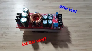
So instead of looking for a component and possibly a capacitor, in most cases we need a separate coil, a diode, possibly in addition to the IC, even external transistor resistors for feedback and of course that doesn't just mean buying much more and therefore also costs more. There is also more soldering and more circuit board space required. and yes, that used to be one of the reasons why many hobbyists preferred to use a linear regulator and just plug it in rather than building a full switching regulator, which required a lot more work nowadays. This is no longer a problem because, on the one hand, component prices are falling and, on the other hand, here are such finished modules, the chip, the coil and the rotors are already ready, usually with a potentiometer with the You can adjust the voltage once and so on. we do it here You see, the thing is no longer really bigger than a classic linear regulator in its old form.
To be fair, it must be said that today's linear regulators have also shrunk, but because linear regulators need the size to achieve it. To get rid of the heat, it is not easy to make it smaller. As with switching rules, we've already seen another problem with sound drivers: this ripple, no matter what you do when you switch, we always introduce a bit of voltage fluctuations into the supply. and with sensitive things like analog sensors or audio applications. This can possibly cause interruptions and also in the other direction because if we turn on and off all the time, that can pose new challenges for the power supply.
A battery with a short circuit. The cable doesn't matter, but power supplies and mains are what you might want, so filter to prevent damage from all this on and off and you might also want the filter for another reason because well, yeah we turn on and off an input voltage. hard all the time, that means a lot of voltage changes and voltage changes on long tracks or cables. If in doubt, it's also called a transmitter, which means it acts like a radio transmitter and can then interfere with other radio devices or devices, if you've ever plugged a cheap switching power supply near an old radio or a historic copper internet router and then he cursed, I went to fix the problem why somehow it doesn't work anymore, he knows what I'm talking about and there is also One last problem.
Yes, I have already learned it. We need a little intelligence to coordinate this on and off, and intelligence does not exist in vain. This brain needs some power and the quiescent current of such a switching regulator. In many cases it can be larger than that of a good modern linear regulator. So what should I use now? The correct answer is, as with technical ones, it always depends, in principle, there is a step like this for many things. Of course it's a very good choice, I have to keep that in mind, especially if you get a finished circuit board like this one, they are designed to be a jack of all trades, meaning if possible they should be able to cover everything. do it pretty well, but only pretty well if you have the sound carrier developed and built specifically for an application and the components optimized for it, you will generally get better efficiency, but it also requires more effort, which means you should always look at whether you want to do the work yourself or compromise with maybe a small percentage of efficiency loss, but you can just use a ready-made circuit board and linear regulators are still extinct, like I said, if you have sensitive circuits or something you have. very, very small output currents or it is idle most of the time, then linear regulators can definitely be better.
It may be an option and even if you have space issues on a board, well, a linear driver is not the best thing in the world. place, but it may be a compromise that is definitely valid. I can't give you a final answer here, but I hope you now understand the differences and understand how it works a little better and can find something suitable as a solution. your own projects and if you keep an eye on all the values, read the datasheets correctly and then configure everything without errors, in the end you will have a power supply with reasonably usable efficiency.
If you're lucky, your circuit will do what it's supposed to do.
If you have any copyright issue, please Contact
![[LANG] Alten Kurzwellen-Superhet von Stefan0719 nachgebaut und modifiziert](https://i.ytimg.com/vi_webp/o-L4zhJ8E5s/mqdefault.webp)