A complete video of an 1.8 MGB engine being reconditioned and modified.
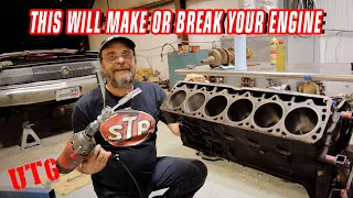
Mar 21, 2024Hello and welcome to the beginning of this vlog. This will be all this mgbb series motor that I have to do. um it comes from a limited edition mgble uh model rubber bumper. The client wants it to be built only for a very fast highway. spec um so there's nothing racey about it we're going to do some porting a fast road camshaft kit a slightly lightened flywheel and a balanced bottom end all the components will be replaced and it'll be a motor
complete
ly documented, so "I'm taking pictures of what it's like right now to write at the end, so I thought you know what I'm going to upload to YouTube too, that's how it will be unless I miss avideo
because sometimes I'm stupid, but this is It's going to be one where it will becomplete
ly disassembled, completely machined, clean everything, all in onevideo
, so the first thing to do is take it apart and do an inspection of the components as it comes apart.
Thanks for. look I came across a small one The problem is nothing major but we were thinking this was the original
engine
but if I can show you one of these it's a standard head bolt washer that's pretty thick and what someone made. was to put two thin head bolt washers in such a straight place. Right off the bat, I know someone had the head removed at some point, but it was also a bit of an eye-opener because when the customer bought theengine
running in the car, I noticed that the cylinder head and bottom end were two different colors , where if it was original it wouldn't be like that but so far I mean it's falling apart okay these are just little things I can tell the customer about so the other thing I thought I would show is that the rocker shaft is ready to come out now so we just lift up the pin and it's a washer and a spring to take the rocker shaft out of this pillar here you have this little grub screw here that holds with one of the heads with one of the rocker shaft washers, so now the rocker shaft can be lifted.
More Interesting Facts About,
a complete video of an 1 8 mgb engine being reconditioned and modified...
I can do it a little bit better, so it's actually pretty tight and then basically all of this will come apart, so you have the rocker arm. If I move this camera back, you'll have a The rocker arm where it's used gets stuck a little bit, then the rocker arm post lines up in that hole there, if I can turn it there, and that's what basically positions everything and the holes for the bolts that go through everything, but now Can I remove all of this and the springs to prepare it for the overhaul and then take out the push rods, this oil normally satin on the bottom because the oil that the cam follows like a little cube, so that gets stuck in there, so That's it, the pushrods might even replace them, not sure yet, so that's the cylinder head.

The customer had a complaint about the oil consumption on this and right away there's a lot of carbon build up on the power number on all the cylinders really, but number four is really bad, but number two is, I think where is it? the problem because it's actually very deep there so yeah we've definitely had a problem somewhere so now that's the cylinder strip so basically the cylinder head components are separate. from the studs, the intake and exhaust valves, the valve spring, the valve cover and then it sticks to the cylinder head because of the um, the oil are these valve spring seats and these just keep them from the spring bites into the cylinder head, if I can get one out. this edge of the cylinder is now ready to go into the acid bath, in fact when it goes through the wash that will remove the seats, I was just trying to remove one so that this is what they look like, they just sit on the bottom of the spring and then there are two collars that retain the valve in the spring, so there are 16 collars because there are two collars per valve.

The next job I'll do is see if I'm reusing the original valves or ordering them. a set of new valves, so I do this by looking at the thickness of how much is left on the edge of the valve. We don't want a sharp edge that stays pretty thick like that, so I would say These look good there, the intake valves are very meaty, the exhausts are perfect too, so the next thing I do is measure the stem where the stems go up on the guide, so I do it by measuring the part that doesn't fit. the guide, but I also know the setup for mgbs because I do some of them, but I'll measure that part there and then I'll measure the entire valve to see if there's any spot and that one has absolutely nothing.
Use it, so basically these will be fired, the stems will be polished, refinished and finished off, but I'll video what happens anyway, okay, so one is hot, I don't know if the camera is picking that up. up here, but up here, it's reading 16 on the micrometer, but as you go down, it's reading 15 there, actually, besides burning a lot of oil, it's in pretty good condition, the guides are in good condition, the seats seem to have been I have been sealing well because there are no really heavy black spots, however I am doing some basic transfers so I will press the guides so I can transfer them around where the guide heads are and for the cost of the guides.
You could also put new guides on it, so the first job for this is to clean it, run it through the acid, clean it, fit it into the lead-free seats, then push the guides out, pull it out and the way we go with that, then What am I doing now is removing the steering wheel and continuing to remove the engine, the two bolts that got stuck there and there I have them quite hot, with the big gun behind them, not the 3.8 guns, now they have come out , all the bolts are undone on this and what is quite interesting is some of the wear, this was supposed to be a pretty good running engine with only a slight oil consumption issue, however when the crankcase came off it was evident that there are quite a few chips in the crankcase, the oil pump gears are very worn and also this is one of the cam followers and I don't know if it is picking up that, but it is very pitted and it is also concave. where it is worn, the camshaft has exactly the same type of wear and some of the cam lobes have almost fallen off, so I can't imagine that it was driving particularly well, that one of them is actually down on the lifter and then the other.
What I noticed is when I look down through the engine I can see that at some point this block has been lined, all four cylinders have a liner so it has definitely been a part before but the really bad thing about this engine is that I can find the magnet, all this stuff that you can see here is a boring chip because it's all metal at the end of the magnet, so it seems to me that at some point in the life of this mgb the motor was disassembled, it was machined to take them to take liners and this is boring, remove shavings from the cylinders that are obviously behind a part of the engine and um and they haven't cleaned it, it could have been an in-situ liner job, which is quite difficult to do, but it definitely did. would do.
To get all the chips out the large m bearings are standard which is good and that journal that is available so far has no wear at all, however the top housing has worn right down to the copper and these are old Vanderval bearings. Also, they are not original bearings, they are lead copper and then when you take the main caps off, the nice thing about these is that they have a number on there, number two, so the number one cap can only go in one place. , the central cover. it only goes in one place, the rear cover can only go in one place and then two and four are marked with two and four, so again, it doesn't look like they've ever had a very good oil change, the Vanderveld bearings again in standard size.
Once you've removed one of the cap bolts, you can use one of them to screw the two outer caps onto the center cap to release it. These are the thrust washers which, again, don't show much wear on the It looks like we found it to be worn down to the copper. I think the fact that someone put in the copper bearings probably saved the crankshaft in some way. The other thing I'll show you because I'm going to put it back on time. -The one minute gap to end the filming is here and here is the oil pressure relief valve, which is a little valve on a spring that moves like this, so that when the oil pressure builds up, the pressure of the oil pushes the valve back and then releases it back here into the sump the mg engine to pull that we took apart didn't do much good so after a discussion with uh paul we decided to look for another engine and start over so that this is uh, this is a The rubber bumper taken straight from a scrap car covered in oil still has all the accessories that go in the trash, I hope, because it is so dirty and oily that it has never had any internal work done, so let's get it.
It's all disassembled, open it and take a look. Hopefully this is better than the last attempt. It doesn't look very good, to be honest, where it was stored in a junk car for a while. The water got in there and, uh, got to work in quite some time. In a bad way, it looks like there was a mouse behind it because it's, um, there's a bunch of mouse-shaped bedding type things, but I'm going to keep removing them and see what the rest of it is like. This is the distributor unit here, which has a little screw here.
It's usually a pain to get out, so I always use an impact driver. This is a snap impact driver, so all you have to do is keep a little pressure on it in the direction you want to undo it and then just give it one. a good blow with the hammer and then it's basically like a spring and a cam here, which drives it to come apart, so now it comes apart very easily and then another little trick to get the distributor and the oil pump out of these engines it's to use the um to use one of the threaded elements that hold the rocker post down so it's a 5 16 unf drive on the thread so we just screw it on and then you can take it out just like that so it's I said that part before, this is a rubber bumper engine and the difference between a chrome bumper and a rubber bumper is pretty easy.
It's outside this faceplate. A chrome bumper is cut here as a different engine mount design, so that's a quick way to tell. the difference between the two mgb engines the next thing that comes out is the front distribution cover, the gear that comes in the mgb, they normally have two different styles, a simplex and a duplex, this is a simplex that is a single chain, this It is the tensioner, it has a spring. tensioner, but we will make it a duplex, so it is a little stronger, so the mgb is dismantled, this is the chrome bumper, sorry, the rubber bumper of the mgb b series engine whose consumption the car is absolutely beautiful, the engine is the complete opposite. unfortunately, I quickly checked it, it has liners installed and showed them the boring bar shavings.
I showed you the wear on the cam and cam hubs, however that was not the worst cam hub after removing them. I have dismantled many B series engines and I think this is unfortunately one of the worst. The slots on this are. Well, I've never seen anything like it. To be honest, it's absolutely shocking that this one here has been worn out. I don't know if you can see the thickness of the wall, this one is warm but not bad, but when you look at the thickness of the wall is half the thickness of the wall, it just wears off at the top, so which started to wear down and then gave it a little wobble, so what I have to do is measure the block because I should imagine that the block is in as bad shape as when I put my finger on it, that's the boring bar that I showed you to all.
I'm surprised before that it didn't go through the oil pump strainer, so this is the strainer here and you can see that some of these boring bar chips just collected at the bottom of the strainer, but the strainer actually did. did. your work just shows that this is an old engine, but that straining straw has been very efficient in preventing Boing bar chips from entering the engine because the bearings don't show the kind of wear that the rest of the engine shows. The crankshaft is in relatively good condition, but if I just unhook the gopro and then show it here, this is in the oil passages, this has come off the crankshaft, I haven't touched it, this is more boring than Bass Wolf, I'll get it back to put there because When I take apart an engine nowadays I do a full report and take some photos with my gopro and send them and I really feel like my client really needs to see this engine, the connecting rods where those chips moved, the connecting rods were destroyed.
I mean those who refuse to put these connecting rods back on, the customer will have to replace them, as I say, the engine has been replated, the rings are all stuck together, it's not in very good condition and in fact I'll show you a little trick. is to verify that the connecting rods arestraight and not bent, you can always tell by looking at this mark here when it is used nice and smooth like this, the crank is straight, if the comrade has any kind of curvature, this would make a zigzag in that direction or that way, it is a good shape Quick to tell if you have a bent rod, but have also had a heat problem on the top of this piston, which is sheared, whether it is due to the bore size of the top of the liners, yes I haven't. boring nor perfected properly, but right now this old mgb is in a sorry state, so what I'm going to do now is take some photos from my ipad and fill out my report.
This is the second engine. The first motor I showed in the teardown had some really bad chip problems and everything, so we decided not to use it. This is the replacement engine I have. Completely stripped down, it's been through the acid, it's been through the hot tank a few times just to get a little more gunk off, but this is it, this thing here is a water drain for the block. It was completely blocked, so I worked. All of these engines suffer with a buildup of foundry sand left at the bottom of the cooling system, it's very difficult to get it out, so I basically work a very long drill bit through the channels and try to break it up and then it goes through this drain as well. um, so that's all flowing nicely now, so what I'm going to do with this is bead it today, um, so that's the progress on that, the other thing that I've done on this.
The engine I'm going to show you now is the replacement pistons and rods that come out of that engine because the other engine had chips in the engine and the engine had been spinning and the chips had been hitting. the side of the connecting rod and it had damaged all four connecting rods quite a bit, so we decided not to use them, so on the spare connecting rods on the spare engine, right now I'm going to recondition them, so I removed three of the pistons. It's number four, so I'm going to show you this sun and this sun and rod press in action and then I have all the different size pin presses and then this arbor here, which I don't know if you can see, has different attachments. which are these and they sit around the piston pin to prevent any kind of damage or breakage and making it impossible to move them so with the piston installed that way we can just turn the pump on and the ram goes down just keep it all nice, tight and centralized, let them take the pressure that way and then with the lever, if we push down, that's what actually puts the strong pressure through it, there we go, that's just released now, so we just hold the press.
Let the pin fully depress the piston and then just release it and then we can remove the connecting rod. My next job on this is to balance the cranks and then recondition them so that by the time there is slight surface rust. This engine hadn't run for a while, so what I'm going to do is because this rod is
being
completely overhauled. I'm going to clean the whole rod beam up and then resize it and all that and check for balance, so I'll record what happens for the new mgb motor or replacement block as well. um it's on the borer.I've tackled one ball, so I have to finish the others. um the customer wanted good quality pistons and The only thing that's available at the moment is the county, but after a bit of shopping around we managed to find some new and older pistons plus 30 ae, so the quality of these is much better. I'm going to have to balance them because The engine is going to be balanced with a fast highway cam, so the next thing I'm going to do is just balance them. I have configured the tool and left it where I have it. I measured the first ball I bought and I have three thousand left to tune, so I let this ball do the others and then cleaned the gasket up, new cam bearings, cleaned all the threads, went over the face of the head or the face of the block and that's it. go the bars reached the bottom of the ball, what I'm going to do is move the cutter away from the hole so the cutters are in the front and then just ease the block back a little, pinch the clamp up, contract the legs slightly of the cat. engage the gear and then just lift up the cutter then use the hook to flip the cutter and then move on to the next ball so that's the mg billboard now so I'm going to flip through the block below and then refine it by appropriate size.
The next job to do on the 1800 mg engine is to grind the top of the block. I have cleaned all the joints upwards. I have cleaned all the core plug holes. The block has been in acid for hours. To clean all the old oil out, but I also went down the oil holes, uh, with one of these long brushes that are there, it's a big long oil gallery show brush, so I went through them as well, so that I'm going to clean the top of the block face up on the skimmer head and then hone it to size, do the cam bearings and then it'll be ready for the final prep a few hours in the cleaner and we'll start assembling it so that's the face of the block. all gone over which took eight thousandths of an inch off the top to get it nice and flat.
The slight difference with the finish on this is that I left it as a rough floor finish. I did it because that just helps grip the joint um it's a standard style joint which I mean it's super soft but it just has a slight texture to it and that helps the joint move. I'll yell over the top of the ball from time to time and then refine it. Size, clean all the thread holes on the dummy head and then deburr and then you're ready for your new bends and final wash, so the next thing I'm going to do on the um mgb motor is hone the ball to the um size.
I took this out. I left about three thousandths of an inch to get it perfect, which will give me the right depth on the right cross hatch finish, so I have it all set up on the machine. Set the stops on the polishing machine so the next thing you want to do is turn on the polishing oil and sharpen so that's the first pass with the polisher so the next thing I'm going to do is check what clearance I have. I have now and we'll see how much we have to remove, so that's it, it should all be the right size, so I'm going to check it now with the ball gauge, like this, like this. that's absolutely right on the right side of the ball so what I'm going to do now I'm going to give it half an hour to cool down again where the sharpening stones were, it creates a little bit of It doesn't heat anything that you can actually feel , but um, and then I'll go over it again and then right after I've gone through it, with pretty much no pressure, I'll go over them again just to get rid of the line. that the ball meter moves in, but that's another part of this whole mgb motor, so the mgb has been through the cleaner a few times and it's been there for about four, five, six hours, so I know that everything is nice and clean and what I'm going to do now is put the recording plugs in and these are fountain style center plugs so with these ceramic holes push the center plug in and then just tap them so that They lie flat and that will block them.
There are four of these in an mgv. one on the rear, three on the side, so while I have the block on its end, I hit the rear core plug, so the ceramic is just sitting on top of that and what I'm going to do is just put two of the plugs on gallery for the ends oh, I don't use ceramic on the gallery plugs either, I use loctite. The other thing I make sure to do when I put the ceramic in is make sure that the ceramic runs into the corners of the gap for the center plugs like this just because if I had a leak it would probably start in the corner which I forgot to do on the mgb is because this it's a replacement block um this here is the engine number so I'm I'm gonna have to put your engine number on the replacement block now every casting all the casting number on the two engines is exactly the same.
It's just the engine number here that I want to replace, so it could be quite a pain to get them out. A lot of people grind them down and then try to rivet them again, but what I figured out is that if you get a really good, sharp chisel and you get under the rivet most of the time, you can get the rivet out and just tap it in. around and you want the chisel to be very sharp so that it stays under the rivet and also doesn't cause much damage to the actual plate, although this plate is not important here because it goes in the trash. so the mgb and cosi need one more coat of paint each, which is a naturally aspirated cosmic i'm building for a guy, so i'm going to let this paint peel off a little bit and then while it's still tacky i'll go over it. with another good coat of paint and they should both look pretty good then okay so on the mgb crank the first thing I do once I have the crank mounted on the crank grinder is make sure it works properly between the chuck and the crank. grinder so we use this dti and i always check it in four places.
I check it on the mains and I also check it on the oil seal faces or where the oil seal will run. What we don't want to do is grind the crank and it would be too far off where the crank will do that on the oil seal which will cause wear and eventually a serious leak, so the first place I'm going to check it is on the front. and rear main and then I'll set it up where I'm checking it right next to this part here and then right next to this part here, that's the crank that's working properly now.
You probably saw that initially I was moving these screws here, these four, so sorry, there are no three. uh there are three screws and what it does is it moves the mandrel so I did it first on the rear and the front main and then on the oil seal and this would basically be where an oil seal would also come off the front pulley , so now I know that's true, the next thing I need to do is set up the fingers because I always do the big ends first, so I need to know what the standard big end journal size is and then I put them here and then that . lift this finger up and then I'll place the rest of the fingers so that it sharpens the crank properly.
The first thing I want to do is I don't know if the camera will catch it. There's a little window here and Basically when I move it up and down there's like a little mark and I want to place it about in the middle so I know I can back off the crank with the stone and forward to cut the stone, what You can pass? could be set up where you only have, say, five thousand strokes to cut because someone has wrapped the wheel around the wheel and worn it out and what will happen is you're just halfway through grinding the crank because the first undersize is um it's the tenth so and then the machine will be hard and it will stop so you won't be able to use the crank so all these basic adjustments to the crank facing are what really matters when grinding the crank , so what I'm doing now is just moving the crank. number forward number one big end so it's aligned with the head of the wheel and then the next thing I want to do is adjust this finger here and then bring the wheel towards the stone.
Sorry, the wheel to the crank nice and easy and then I'm letting the crank grinder sit on this finger here and then I look at the gap on the wheel and I move the wheel towards the crank so what you can see Here's how bad the crank is, it's pretty marked. bad, so what I'm going to do is write all the crankshaft data now to know what I have to rectify and then I will show part of the well-ground crankshaft. My mgb crank is ready to grind now so what I'm going to do is show you how cool it looks when it starts grinding.
What I'm going to do is I'm just going to bring the foam in now, so what am I going to do? What I'm going to do is in this box here on this dial here is where it started to cut into three and what I'm going to do is as a reminder I'm just going to set this dial that right now this style is to do the power grid so this is redundant but If I put it on three I'll know that three is where this crank started to cut and then what I'm going to do is come on half a towel at a time.
I'm not going. to rush it, I see a lot of people trying to overbite a crank and uh, no, I don't agree with that, take the time for half an hour at a time and also do it as is. It comes as the crankshaft goes down like this, so now I know I've got a tooth out, what I'm going to do is move the crankshaft on the radius on each side, so we're going to do the right thing. The hand side first and that's the noise where the width of the wheel side needs to fit on the crank side and then what I'm going to do is take another afterthought and then start moving to the left side , so that's the big ends are ground in the mgb, so what I'm going to do now is activate this part of the machine thatgrinds the electrical grid.
I'm going to set up my continuous meter, so I'm going to set it where it is, uh oh. needs adjustment, where it shows that I need to remove ten thousand, that's the crank ground and polished and it looks absolutely stunning once everything's been polished and everything, so what I'm doing now is letting the coolant spin. the wheel and now I'm going to polish the crankshaft, so the first job I have to do is take it off the crank grinder and then weigh it and write down the weight on the customer's work sheet that I wrote down. what the connecting rods fit and what oversized bearings I'm using, so now what I'm going to do is balance the weight of the crankshaft between the pistons and the connecting rods and continue with the build for the next job. for the mgb it is to balance the crankshaft assembly, so what I am going to do first is balance the crank.
I put all the details of the cranks on the balancing machine and then the computer is calculating the external balance, so I'm going to pause. It is because it is calculated, turn off the machine. I'm going to print out a working copy of the initial balance, but it basically tells me that this side of the crankshaft is off 29 grams at 220 degrees and this side of the crankshaft is off 14 grams at 25 degrees, so the next thing I have to do is plot where is that on the crank and then remove some metal. Now I'm quickly checking the balance of the front pulley and that's a little bit out too so I'm going to pop it in and there we go, that shows how sensitive the balancer is with that little drill mark that brought that side of the crank just right. in the The next thing I will do in the mgb is balance the pistons.
I found the lightest one and reset the scale and now right away I want to say these are new good quality pistons and this one weighs 3.2 grams so I'm going to have to lighten that up and then the next one we'll check out is this one that weighs 1.3 grams , so I'm going to take a little bit of weight off of it and that one also weighs 1.6 grams, so I'm going to take a little bit. of weight off of that too, so the first one I'm going to make is the heaviest one, I already took the rings off and I'm going to take the weight off, in fact, I'll show you now.
What I'm going to do is look at a lot of people who have tried to drill holes down here, lightning bolts over here and make a mess trying to polish them by hand and all that, but I'm going to put this on the lathe and then Very carefully, just remove some of the weight of this boss here, even if I take it to where this original machining part is and then take it over here and hopefully that should take off the weight that I need, so what? What I'm going to do is leave the rings on the scale and then keep going back and forth once I've machined it so that the pistons that weighed three and a half grams are now down.
Oh, I'll just show you point eight gram. If it's less than a gram, I'm pretty happy with that and especially since it's just a standard road engine with a cam and a slight gas flow. This is a Sunday car, basically, um, so as long as it's under a gram, I'm very happy with it and I'll show you what it looks like once it's been machined so there's a piston that it doesn't have. It hasn't been machined and then I set up the lathe to have a really nice radius and then I took a little bit of weight off it, close to which isn't much, actually, I mean, if I compare it.
On that one there you can probably see the difference, but it's enough to get them as close to zero as possible. The next thing to do is to recondition the connecting rods, so to do this, I have already shot. I ruined them because I wanted to just clean all the little bits of rust off of them and turn them back to cast iron and I could see any imperfections and stuff like that on them, so what I'm going to do now is first. of everything, balance them because the engine is balanced, even if it is a standard balance or a standard road engine.
I'm still going to balance the rods, after that I'm going to change the standard crank nut to an arp nut and then I'm going to tighten the cranks and then I'll check if I need to resize the cranks to see if there's any ovality or shrinkage or something like that and then the last thing I need to do is just check that they're okay. Seriously, the next job I'll be doing on the mgb is putting on the new arp big head student nut kit and also checking the roundness of the rod ends, so the first thing I'll be doing on the mgb rods is taking the original bolt and nuts, so I just unscrew the nuts and then with a copper leather hammer just tap the original bolt to get it out, then what I could do is just make sure these two faces are really clean, they smell like acid, actually, so we've been in the acid bath um and then the next thing to do is check that this radius on this part of the crank here doesn't interfere with the harp shoulder because we want the harp bolt to pull toward down the flats, not the shoulder or the radius, so it's just a case of adjusting them and then checking them, but what I'm going to do first is just clean all the faces and just give them a quick wash, so I'll start and do that . what do I have to do, I washed all the rods, I made sure there were no burrs, I cleaned them all, I just gave them a little bit of emery before I measured them, I made sure that this oil four jets uh unblocked and um, so what what I'm going to do now is see how they fit so I'm going to use a little bit of arp grease here just to help them go down and then make sure I have a lot of clearance so what I'm going to do is I'm going to mount one and then I'll discuss what I'm doing a little bit. tighter um I've talked to all the cranks I've put all the harp bolts on and taught the bolt so the next thing I want to do is measure this circle here so when you look at a bearing book I thought I'd talk about the bearing books because they can come.
It seems a little complicated, but what we have allowed me to try to focus it a little better. What we have at the top is what is the bearing, what is the layout of the crankshaft, what is the material, what is the diameter of the crank is the outer diameter or the inner diameter of the casing on the connecting rod and the mains and then the thickness of the bearing, the width of the bearing, so what I'm looking for is in the mgb. I want to measure this part here on the connecting rod. So I go right to this column and I go down to the big ends, which is aeb, and then I look and the bottom tolerance is two inches twenty one thousand and the top tolerance is 2 inches 21 and a half now, so I've set my dti to the lower tolerance so basically what I want when I measure the crank is for it to hit at zero or it can go over half a thousand so to do that I set the dti that I'm going to Put the soft jaws back in the vise because I don't want to grab it.
Oops, I don't want to grab the crank and mark it, not like I would because this vise actually has soft jaws, not grippy jewels, so with the buddy in there, so what I'm going to do is just put my gauge on dash, I don't know how much this is going up, actually let me move it over there, so I'm going to put my ball gauge on the crank and then I very carefully measure the size and that there is absolutely a bump at zero. Let me see if I can show you here what I'm going to do is measure it in a few different positions, so I'll measure it there. measure it there and I'm going to measure it there as well so it's about two tenths over so it's still within tolerance and same thing with that so that's the crank okay all I'm going to do next is check the righteousness of that comrade. has failed, there's a thousandth of an inch tight here, uh, and I already set this to the lower tolerance, so I'm going to re-machine this same one with that one that's a thousandth tight and that's in place, so two.
Okay, two league machining, so to machine them we go to the crank house, which is very fortunate about this is that the cranks are tight, so it's just a matter of machining the metal of the crank, if they were too loose, I would have to reduce them. the circle and then re-machining it through which I'm sure I'll end up making a set for you to see, so I've set up the crank at home, if I stop it I can explain it so basically this crank The chuck is connected to this pedal down here and then when I press the pedal, it expands the stones and then places them.
It basically tells you how much you can remove here. I mean, most of it is done, but I think I'm fair. I use the gauges as a guide on where I'm going, but I don't rush, I take my time, I try to keep the dipstick as cool as possible and I keep a little honey oil on the stone, so what? What I'm going to do is get this rod to the proper size and then I'm going to put the pistons on the rods correctly. The next job on the mgp is to place the pistons in the connecting rods.
Now these are an interference fit design, so what? That means the connecting rod is too small for the pin, so the only way to get them in is by heating the small end of the connecting rod. You can do this with an oxygen-acetylene lamp. It's not really the right way to do it. But you can do it. I use this solar and rod heater that I've had for a few years. It's a brilliant machine. The model number is CRH 50. So the first thing I do is mark how the connecting rod fits on the piston. I always keep the pin in the front of the piston before I install it and then I'll know the rod fits that way so then I'll put the rod in the connecting rod heater like this so when I take the rod out take it out and put it in then the complicated thing is that you have to be pretty quick to get the gujjan pin into the crank without it breaking.
If it tightens, we're in trouble because then we have to try to push. cons here for everything to connect basically so yeah it's not good so while the rod is heating up I'm making sure I have the right type of punch to press it in or slide it in I'm going to make sure the bolt pin Even before mounting it on this machine, the piston floats in and out very easily and then what I do is once one rod has been in the rod heater for a while, I put the second one in. I also installed the pistons. cylinder order one two three four and then I did the same thing with the connecting rods, so now I'm going to put that one in there and then what I do is you can buy temperature wax to control the temperature of the connecting rod, but I mean I've done some now, so I can almost guarantee that the side where the temperature is correct by watching the beginning of the discoloration on the end of the rod, what you don't want to do is blue the rod. or take it where it changes color too much because then it's no good, let's install them, that's all the connecting rod is mounted on the pistons now, so what I'm going to do is when it starts to cool, I'm just going to put some on. a little bit of um 2050 oil in there to soak everything around the uh gujjun pin and the gujjan pin boss on the piston, so now they get quite hot because the heat is dissipated through the piston and the rod, so In Actually, now I can't do anything with them until they cool, so on the mgb I've just been collecting some bits from the dust layers, which I think would be what will make it look pretty good, so I've had the Powder coated front cover and crankcase too so love the car really nice and new so with the mg I have the rear plate on and I've done that so basically I can bolt the engine to an engine.
Stay with it, all I'm going to do now is turn it over and separate the piston rings, pistons one and four are put on first and then I've used the arp piston ring compressor to put them on, these are fantastic. Then I made sure to put some arp lube on the big end bolts or put a nut on the thread and under the nut so it doesn't pull. I then used my arp stretch gauge because the bolt nut needs to be stretched. at about six thousandths of an inch, they recommend it be 35 foot-pounds, so what I do is I always zero the gauge, go to 35 foot-pounds, and then measure the stretch.
I've been doing this for a long time, so they are very accurate. most of the time, but in fact all the time they usually don't get it wrong, so once that's done, what I have to do. Oh I also have the rings so what I have to do now is crank the engine and then repeat the process on cylinders two and three um and then I'll show you what I do on the oil pumps modify the oil pump um and the reason for that is that they don't flow very well mgb oil pumps um there is There is no pressure side to this pump other than the pressure that the pump generates since in the pressure relief there is no pressure relief in the liner , this is just what the bomb produces, but I don't know if we can see it in Oops, I don't know.
If we can see on this bomb, but down here, yeah, it's just a matter of picking it up, I can see that they are launch marks, which is not good, it's very dirty, I mean, there are no pieces to break, but even in that well, uh, even in that port. There's just nothing pretty there, so I'm going to sort all that out now, basically how this works is let me take the strainer, the straineroil sits at the bottom of the sump like this, the bottom of the oil pump then sits in the a strainer like this and then the top like this and that's what feeds the engine, so basically up to this hole here and all of this needs to be fixed and then base it, so what happens is once it gets to this part of the pump, then it feeds the bottom of the pump over here so it goes up here and then it goes into this part here and then run through the rest of the motor so it feeds the bottom of the pump through this here from the strainer and then it works its way through here and then it feeds the rest of the motor through that little port down there and as I just I mean, it's full of oval casting burrs, it's not very pretty at all, so I modify them and I also modify them so that it feeds the top of the oil pump as well, so what I'm going to do now is take this to the gas flow room, tidy up this hole down here, just drill down there a little bit, tidy up your pool over there, tidy up everything at the bottom of these ports here. make sure there are no burrs that can catch on the gear and then that is the oil pressure relief in an mgb engine is done through a plunger and a spring that sits in the engine in the oil gallery main and then when it builds up enough pressure, it basically pushes the oil pressure, it pushes it back and then once it gets here, there's another, there's another hole in the block and then the oil just runs right into the sump, This is how oil pressure works on an unleaded seat with mgb adjustment.
So these are the unleaded scented steel seats and I'm going to put them on the exhaust side of the cylinder head so I installed a machine to countersink them and get the seat out and then what I'm going to do is just gently move the cylinder head just to improve performance because it's running a slightly
modified
camshaft so I'm doing great with the mgb cylinder head but Sam and I or Sam Crossflowing we just stopped for some lunch so I want shout crepe o'clock in Newbury. If someone is a newbie and wants to eat something tasty, that's the place to be.I'll show you what we do. I have good bacon and egg so the next mgb job is to press some new entry guides so I'm using my comec machine for that and I don't need to take a measurement for these because I already have Prefab with the correct spaces for the entry of mgb, so I basically set up the machine, compressed the old guide directly, that's the new intake guide, installed the cylinder head that I just spent all day modifying. As a failed pressure test, when gas was flowing, it had a lot of porosity in the port, which I noticed, but didn't think it would be a big deal, so I went ahead and that was the final check for me.
To pressure test it again, it passed the first pressure test before the gas blow was done, but that's the problem with these old castings, you can get a little porosity and it's game over, so I just removed another cylinder head to do it. that in the morning so it's on the acid right now so while it's on the acid I'm going to go ahead and just fix the oil pump so the first job is to drill the main feed to the pump so I'm going To do that by simply holding the pump in the vise and then letting the drill follow the original hole until it reaches the bottom and that's it, I've drilled down to about 10 mil below that pitch, so what?
What I could do now is do the rest by hand with a grinder, just finish this end, but the big step that was in this main feed is now pretty much gone, so I'm happy with the first stage, so that's it. the pump flowed a lot now, everything is nicely rounded, all the flashings are out of there. I have polished it completely. I bought the main oil feed to the pump and also gave it a slight relief at the top. Basically it will feed the bottom and top of the pump, so the only thing I'll probably have to do is raise the spring on the oil pressure relief valve a bit to compensate for the slot at the top. but that's all I can deal with later yesterday, final checks on the mgp cylinder head that I had spent hours moving and fitting unleaded seats.
When I did the final test, it had some porosity and was leaking. on the pressure tester, so it wasn't good to use, but since I had spent a lot of time on it and I'm going on vacation soon and want to finish it, I was a little fed up and threw it away. It's right in the bin, so today is another day. I've relaxed a little bit now, but I was going to take it out and show you the hole in it, but I'm not going to jump into the bin and it's a little too much. very far, but there it is, so yeah, it's a waste of probably five hours of work, but there we are, it's better to check them than to ship them and they leak water once they're in a car, that's the problem. uh, port on old cylinder heads, I guess, but on the next cylinder head at least we had a spare or at least Paul, my client had a spare, because the engine was in such bad shape that I was able to get his original engine back with the chips. , now I've used what was going to be just a replacement head unit for it, um, but yeah, now I can use that head unit to make another head, so last night I quickly took it apart and took out the valve guides. of it and I dropped it in the acid because it was in a little bit of bad shape, so I'm fine, I'm going to take it out of the acid that's in my shed, flush it, pour it out, I'm going to port it.
First, like I said, the guides are out, so I'm going to port them first and then I'm going to do a pressure test before I spend time putting seats in, which I probably should have done the first time, but no. come on I didn't do it so we'll see what it looks like when the acid comes out so the next part of the oil pump is for me to assemble now now that everything has been through the cleaner just make sure it still no more clogs there make sure everything is nice and clean so that's the body of the pump and also the top of the pump because I've been because I've drilled here I want to make sure there's no chips down there that they can Um get in the way everything's been blown up anyway and then the next thing is to lubricate the pump body so what I'm going to use for that is just a little bit of 2050 running in oil and then everything the way. the pump body and then down at the bottom ready for the first rotor to go in then with a nice clean rag just make sure the two pump rotors don't have any rust protection on them I mean I've already gone I go over these once to make sure they are clean, but this is the procedure I do on all engine versions.
I always take the pumps apart and double check them and then what I do is prime the oil pump with the version. lubricant and then what that does is everything, immediately the pump creates a vacuum to suck the oil out of the thumb a lot of times these pumps run completely dry and what that means is you usually have to do it. then try to backfeed the pump to get the oil out of the sump into the pump so by priming the pump with oil as soon as the engine starts turning it will create a vacuum and draw the oil out of the sun so I also make sure that I fit it in I put the oil in both rotors the next thing I thought I would show was this part of the gasket here what I always do is just make a mark with my finger on the gasket so I can cut that little bit off so there is no restriction on the pump , so that's the second cylinder head for the mg or the gas flowed after the first one was porous.
Well, good news about the butt that happened, that's the face of the butt, all set, so what am I doing now? it is rubbing on the flywheel mg, as you can see here there is damage from the rivets that attach the friction material to the actual plate, one of them must have come off or loosened or the clutch was so worn that it has been hitting the rivets. on that beautiful yes it's pretty bad but it's milled really nice now they look amazing once they've been on that machine so I'm getting close to the end of the mgb engine I've got the cylinder head bolted on I set up the valve spring installed correctly, uh, I connected all the valves on the back, tested it, all the gas flowed and I cleaned all the bolts, so the next job I'm going to do is set up the vernier. timing wheel is a vernier timing wheel from Kent Cams, but what I always do is remove the chain and pulley from the crankshaft and then check for end float on the camshaft with the vernier, so I put a dti on it. and then I just put a little bit of pressure on it and then I lever it back and forth just to measure how much final flow it has and it's got about a thousand and a half so okay the next thing I do is check that the gears are aligned . perfectly um the mgb crank has little shims on the back of the end of the crank there or on the back of the front of the crank I should say behind the blade keys you can assume these are machined perfectly and you know what cams Kent the material is usually perfect but it's always best to double check one thing that's always pretty tight on these is the crankshaft and the camshaft pulley is always pretty tight so I always clean them . a little bit just to make it a little easier and then with no chain all I do is use a nice flat steel ruler and rest it against the gears to make sure it doesn't come off too much that's it now what I can do . is to get the timing roughly right, so around there I'm going to set the timing on this camera with meters, so as long as it's pretty close, I'm happy with that, I'm going to put the chain on now, and then the next job.
What I'm going to do is build the rocker so I'm using a new rocker here with the old one with the old rockers installed so what I'm going to do is use liquid molle build grease for this and make sure put enough grease on the rocker shaft and then also on the ball and on the tip of the rocker arm and then I'm going to put some on the tip of the valve, just move this towards the bottom of the pushrods and just make sure that It is well covered with grease so that at the initial start we do not have problems with it.
What you may have noticed is that I had to remove it again because I put it in, I forgot to put these two in. little shims under here and what that does is just lift these two posts up a little bit and just put the shaft under minimal pressure and then I made sure I had enough liquid molybdenum. grease the rocker shaft under the rockers under the push rods so the next thing you need to do is put the head down because even though the head is on it's just these outside bolts that hold it on not the head bolts head that are on the rocker posts as well.
To lock the rocker shaft in place there is a little screw right here that has its own special washer that actually has a flat part there as well and that prevents it from unscrewing so we need to make sure this happens first and then with A A little harp grease is important, then just put it on the platforms so the washers and everything can turn on them if necessary and not catch to give you the correct torque. You can also use like light engine oil for that, but the right grease is always better, so the timing chain is now on and approximately in the right place.
I need to set the cam timing because it's a
modified
cam there, uh, I need to go get some washers and some new uh 5 16 unf nuts for this part of the rocker shaft and then I'm going to tighten the entire cylinder head to the max. down, um, adjust the tap, you'll time the cam and then you'll finish dressing up some parts, you'll put the motor plate back on, you'll put the flywheel on. but it has to come off the steering wheel support so it will go last. I used to be able to lift these motors by myself but not everything gets heavier anymore.I also have to put the tank and chain tensioner in the front. the locking tab for the camshaft and the crankshaft, but what I'm going to do is continue making these bits. Also on the end of the rocker shafts you have a spring and a flat pin and then two split pins for between there and there so I'm going to get those now too and do them a little bit forgive me so don't forget it's time to talk calmly about the head now, um, the torque wrench setting for one of these cylinder heads is 50 foot-pounds, but what I'm going to do is do it in stages, so first I'll go to 25 foot-pounds and then basically in one of these, I do it like it's a swirl. that just works and the reason I do 25 foot-pounds first is because once I have 25 foot-pounds of torque on all the nuts, I'll check the nuts in the center that hold the rocker arm shaft down as well. deep socket on these because this extra bolt that cannotice here and here compared to here and here this is what the rocker shaft is then bolted to which has small long nuts that lock the rocker shaft or rocker cover, sorry about that. so these ones, I'm going to turn them down so they're up to 25, so I'm not going to pull the torque wrench like I did before, just bringing it down nice and steady, down to 50 and now I'm not going to be as aggressive with the torque wrench so soon. how I approached.
I'll then try to put the same amount of pressure on the torque wrench and then quickly make sure everything else is fine, which it seems to be. this doesn't really move, normally the center couple moves a little more when you put your head down, yeah look that did it and then it goes back down to 25 to check the rocker arm nuts one more time and that's it, so I have the faucet. Now it's in the block and the next thing I need to put in is the oil pressure relief valve, so I put that in just so I can get some lube down there, but if I take it back out, basically once the engine builds up pressure and then pushes the plunger back against the spring so the spring is what controls the pressure and then once it passes this little hole or rather this hole down into the pressure relief hole, The oil then flows back to the sump. of the engine, the tap clearances or the valve clearances for this cam, this Kent cam, the valve clearances for this are 16 mil, so I have the feeler gauge.
I have it where cylinder one is, it balances on the intake and exhaust valve. so I'm going to set cylinder number four so the themes are set. The next thing I have to do is camshaft timing. Cam timing is done by adjusting this vernier timing wheel so the first thing I need to do is find trudy tvc and then I'll do one full revolution, well two crankshaft revolutions, one camshaft revolution just to make sure that I'm still at my pointer, so the next thing I need to do now is find this full lift on the crankshaft. degrees on the intake valve so I know it's going to the exhaust inlet on this mgb so I'm setting it off the intake valve and what I'm going to do is crank the engine until the intake valve starts to open and then I'll slow down to take my readings so I want the figure I'm looking for to set the time to be 108 degrees so right now it's at 95 degrees and I want that 108 so what I'm going to do is do is undo the vernier timing wheel, so what I'm going to do now, even though it's a little painful, I'm going to move the um, I'm going to move the vernee around one tooth the reason I'm doing this is because I have the right time but I'm right on the vernier stops um and that bothers me a little bit to be honest so if I move it one tooth I should put it right in the center of the vernier so with a little bit of fiddling with the vernier moving it over one tooth, I now have the timing set to exactly 108 degrees, which is what Kent Cams recommends. uh the tappets are set to 16 o'clock which is also what Kent Cams recommends so I'm going to record this on my engine build sheet so I can go back to it in case I ever need it so all I have to do now. is placed on the timing chain tensioner, remove the carrier from the front, tighten the rest of the vernier bolts, tighten the cam, camshaft pulley, bend the locking tab and put on the front cover, put the water pump so that the last thing I have to do on the mgb is install the distributor unit.
This is quite easy to do. You can use an old rocker bolt or an oil pump bolt or even just a 5 16 long bolt so just screw it into the bottom. That's because there's a 5 16 unit thread on the bottom, lubricate the entire bottom of the drive up and then you have an offset dog with the engine on at number one, so TDC with the rockers swinging like this, it What he wants is this displaced dog. pointing up like this and there we are, and then if we could, we could put a line from there that would go to number one, so the next thing I have to do is fit that in, but I'm going to give it a y. come up first so this is it this is the full mgbng a quick summary but you would have seen it in this video my client i do enough work to beat your garage let me do paul's engine overhaul so between Me, the beach, will it be your garage and Paul?
We have kept in touch about this. Fortunately, the first engine had poorly installed liners. They had left boring chips in there that had destroyed everything I hope the video shows of some. Months ago on the strip we managed to get another late mgb engine to recondition. The Ae pistons are very difficult to hold, but luckily we found a plus 30 set for that. Then we installed arp big n stud and nuts. had the rocker cover and the front cover powder coated and shot peened right on the road um then we had problems with the cylinder head our gas flowed through the first cylinder head only to pressure test it at the end to double check it and I found out it had a porosity crack, so it immediately went to the bin, which I didn't like, so this is another cylinder head that comes on the second engine, a new set of valves, AE valves, new rocker shaft gas flow.
New valve guides converted to lead free. I used the original bolt and nuts on the cylinder because they were in very good condition and the old original material is actually better than the remanufactured one. I made a high flow oil pump. I reground the crank to balance it. The engine re-grounded the steering wheel and set the tap to the Kent Cam procedure, so I want to shout out to Andy at Kent Cams for supplying the Ken to Sorry, the camera and the vernier for that um, yeah, time of vernier and wheel, so I. We've set the cam timing exactly to what Ken recommends and then all the engine parts were supplied by Simon at Nevlock, so when it comes to bearings, gaskets, pistons, everything really the swingarm, everything else, the oil pump comes from Simon in Nevlock. just quality parts, as always, so that's it.
Now I'm waiting for Andy to come pick up the engine to take it ready to install in the car. The car is absolutely lovely. It is a later version of mgb le. I think this is going to work. It will be a pretty long video. I hope you managed to persevere and see it through to the end. I wanted to do a video of a
reconditioned
engine from start to finish, so this is what will probably be next. be a cosworth or a vauxhall my local and normal suppliers so nevlock kent cams um and shop blow up everything the guys supply and do is amazing so yeah thank you so much if you could leave mgb comment below it would be great if you are seeing this and not yet you have subscribed.If you could subscribe, that would mean a lot to me. I think the next vlog after this will be a workshop update, so, a lot has happened there. Hopefully that will be a pretty good video too, stay safe, see you all soon. Remember to comment. Remember to subscribe. Please, I'm going on vacation, so I'll see you in a week. Oh, I'll walk through it. engine i also want to thank jeremy from liqui molly for supplying the build grease for the top end of this engine so thank you all
If you have any copyright issue, please Contact