Science of Simple Spans of Floor Joists
May 08, 2024the
science
ofsimple
spans
, let's learn about thescience
ofsimple
spans
and this information was provided by glenn mathewson, consultant and educator at buildingcodecollege.com, maximum beam spam seems like a pretty simple concept, but there is obviously a natural limit on regarding the length of the wood. It can extend without breaking under a particular load, but when inspecting a house we don't want to see anyfloor
joists
approaching that breaking point, we don't even want a joist to bend that much, so when we talk about maximum joist it encompasses as defined by the international residential code, we're not really talking about pushing things to the limit, but rather we're largely talking about what it takes to have a functionalfloor
, one that doesn't bounce around too much or make noise when we walk on it.
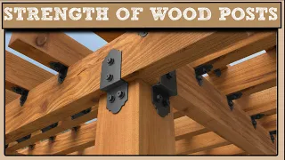
Take a look at this sketch about beams. Charging light. Compression and tension loading. A beam creates a bending stress that puts the wood fibers at the top in compression and at the bottom in tension. The height of the beam and the species of wood affect how well it handles them. emphasizes that taller beams and denser species deflect less and allow them to spread more. IRC span tables make it easy for contractors and inspectors to choose a beam to join a single span without intermediate supports or cantilevers or to obtain the largest single span from the lumber.
More Interesting Facts About,
science of simple spans of floor joists...
Lumber is available, but span is only one of many related functions. with the beams. There are other rules for locking notches and bracket lengths, and all of these features can be read alone, but when taken together and mixed with a little science, they start to make sense, and not so arbitrarily. rules, but as a means to their intended ends, home inspectors don't need an engineering degree to understand how these various joist-related code provisions work together, so let's discuss them informally, the first step in designing a floor system for a house is to determine how much you expect it to support and that is, the heavier the load imposed on a joist or joist, the shorter the distance it can safely and functionally span, this shortening should not be Because the code is worried about the floor breaking, it doesn't.

If you want too much bend, bending rather than strength is the main limiting light in conventional wood frame construction. Maximum deflection is the maximum that a building system or component is allowed to bend under its maximum design load. Historically, the floors have been kept in l divided by 360 where the length of the beam in inches is divided by 360 and the maximum deflection allowed for a given section is obtained, we can consult table r 301.7 and the irc. We can also take the free internachi structural problems online course for home inspectors to calculate the deflection of a beam as an example for any 14 foot beam, the deflection limit is about half an inch i.e. 168 divided by 360 approximately the deflection limit l divided by 360 for floor
joists
exists for at least two good reasons: one, it should prevent the drywall or gypsum ceiling underneath from cracking it is also about how stiff the occupant expects it to be feel the floor when you walk on it, while a trampoline can withstand the live load of 40 pounds per square foot prescribed for residential areas, it would be a rather impractical kitchen floor if it were more.
If deflection greater than l360 were allowed, the spans Allowances would increase, but the floor would not be as rigid. If you apply less than the maximum allowed for a given beam, it will deflect less and feel stiffer, so what gives a beam its stiffness when a load is placed on it? In a beam, the fibers at the top of the beam are compressed and those at the bottom are under tension and in the middle, what engineers call the neutral plane, these forces decrease the ability of the wood fibers to resist be wrinkled by compression or stretched by Tension directly translates to how much a beam deflects and is why denser wood species can spread further, resist stretching and creaking better and therefore deflect less .
Still, height can compensate for a species' deficiencies the more mass is distributed. away from the center of a beam or toward the edges of tension and compression, in other words, the taller the beam, the better it resists deflection, so a two-by-ten can span more than a two-by-eight of the beam. same kind of gradient and this is also why i can span extreme distances without a major increase in depth, much if not most of their mass is in the upper and lower wings. These tensile and compressive stresses are also what move the load to the ends of the beam to transfer it to whatever is below, usually hanging beams or plates and for this load transfer to work, the beams must be maintained in a state of tension. , an unstressed beam is a deflecting beam, beams will lean on work if they are allowed to, and a beam laid flat as if it were a platform cannot extend very far without bending along its thickness, given The way houses are built, that's not what happens, but rather the beams, especially when overextended or overloaded, try to fall in the middle of the span.
The thickness of the beam is a large part of what this type of drop presents, while the height manages the stress. The thickness of the beam helps keep it upright and manages the stress. The relationship between thickness and height is important and most obvious in beams where additional plies and larger sawn thicknesses are common; On the other hand, sawn beams no matter how tall they are are always an inch and a half thick, so although a sawn beam can withstand more tension as it grows, it also becomes more difficult to keep it upright thanks to other code provisions and common sense, the width of the beam does not have to do the job.
It is only the blocking of the edge beams or beam supports at the ends and the locations of the supports that ultimately keep the beam upright and stressed. 502.7 in the code will help, in addition to supports also supporting the vertical load, these other features almost exclusively make the blocking and edge beams resist rotation when the height of the beam compared to its width is greater than 212, the Width cannot keep the girders upright along their length and the bridge is required to be blocked within the span to prevent the girders from overturning. Home inspectors are not code inspectors but housing inspectors.
Inspectors can pull out the code book and look at the science. If you want a stiffer floor with less deflection, you just need better stress management. You could use higher beam heights, denser wood species, or tighter spacings between beams, or you can add bridging locks with the span to reduce beam rotation in the middle of the span, so let's say you have a 2x10 beam that is slightly overextended. Its main fault is excessive deflection and the usual reason is that it wants to fall in the middle of the span, the same principles that stiffen a flat upwards.
Code deflection limits can stiffen a floor that exceeds the span up to the deflection limit. The code will tell you this, but blocking the bridge can cause girders that slightly overspan to be within deflection limits and that is a more reasonable alternative recommendation than replacing the two by tens. With two by twelve after deflection, shear is the next stress that the beams must be able to withstand, but it is generally not an important consideration in wood beams, the shear stresses are distributed in the opposite direction to the bending stresses, they are greater along the horizontal center of the beam. neutral plane and increase towards the extremes.
Shear failures and sawn beams generally appear as cracks that start at the ends and propagate along the neutral plane, that is, along the grain, and this type of failure would be problematic because two small beams do not equal to a large beam, each smaller piece deflects more than a large one would, but it is very unusual for a canted beam to fail and shear along its length, shearing across the grain is even rarer , if not unheard of, because of the way the fiber is oriented, it is much easier. It is better to split wood across the grain than to cut it across the grain.
Research has shown that beams will fail and bend long before they fail and shear, so even though the shear stresses are greatest at the end of the beams, the IRC allows the ends of the beams to break. Notches should be made up to one-quarter of the depth of the beam. Notches are not permitted in the middle third of the beam where the bending stresses are greatest and in the rest of the beam where the bending stresses are least, they are limited to one-sixth. Meanwhile, joist depth holes are allowed two inches from the edges anywhere in the span, indicating how little to worry about when it comes to shear stresses.
We also have to think about support. Once the beams are loaded they have to transfer the load vertically, the key here is to prevent the beam or the member the beam rests on from being crushed. Wood is more easily crushed along the grain, such as where the ends are located, than parallel to the grain, such as a post the size of the support area. What is needed to prevent crushing is directly related to the strength of the beam, what it is supported on, and the total load being transferred. Spreading the load over a larger area reduces the load at any point, which in turn can allow for higher loads.
It's like snowshoes. Distribute your weight to prevent sinking into the snow. This is another fundamental of engineering. The IRC simplifies beams that are supported by wood or metal. Code Section 502.6 requires that the entire width support at least one and a half inches in length this minimum area. of wood necessary to transfer the loads that a floor designed using the prescriptive IRC tables can generate without overloading the beam and crushing its ends. The minimum support length on concrete is three inches, but this longer length isn't about the wood, it's about the concrete. The support of the beam on the concrete creates stresses that can cause the corner of the concrete or masonry to crack and detach or break under the beam and the three inches of required support distributes the load over a larger area to reduce the possibility of spalling and leaving enough area behind the compromised edge for the beam to be safely supported if it occurs, this information was provided by glenn mathewson, building consultant and educator buildingcodecollege.com.
I'm ben gromicko from internachi, which is the international association of nachi certified home inspectors. org thanks for learning about the science of simple sections
If you have any copyright issue, please Contact